
Monoceros for Grasshopper / Documentation
Documentation
The complete data type and Grasshopper component reference.
Current plug-in documentation, maintained with Monoceros 3. Examples and downloads are for the Grasshopper plug-in.
Monoceros 3 is a Discrete Assembly plug-in for Grasshopper / Rhino by Ján Pernecký. It fills a spatial Envelope with discrete Modules according to user-defined Rules using the Wave Function Collapse algorithm. New to Monoceros? See the Quick Start guide.
Bare minimum ↓ GH
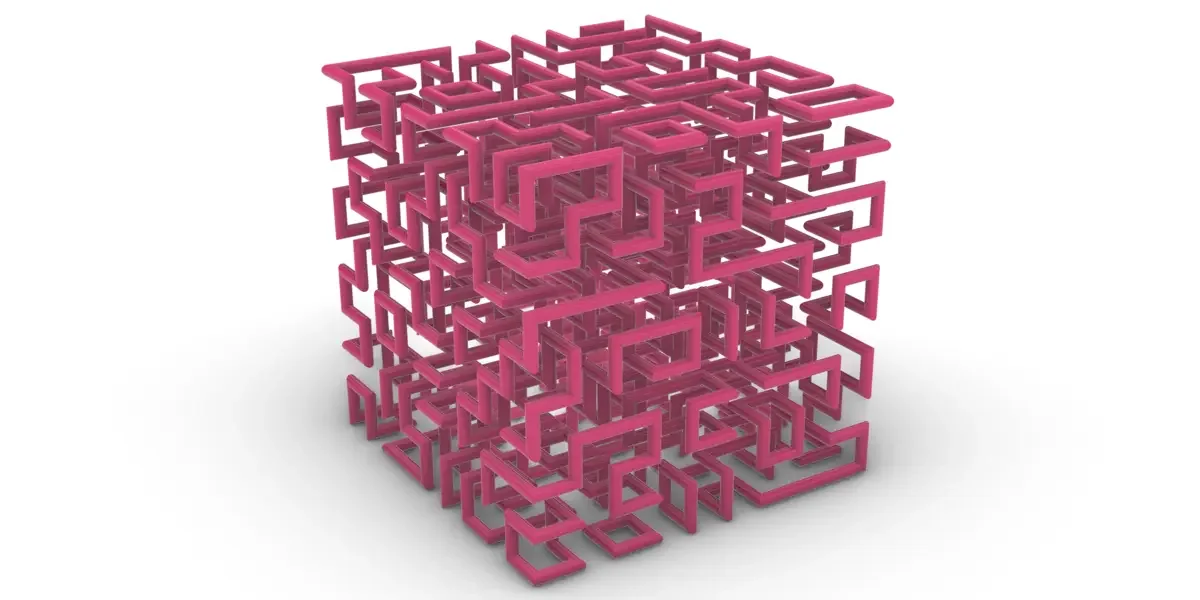
The simplest possible Monoceros setup - one module, one rule, one solver call. Grasshopper file for download.
Puzzle ↓ GH
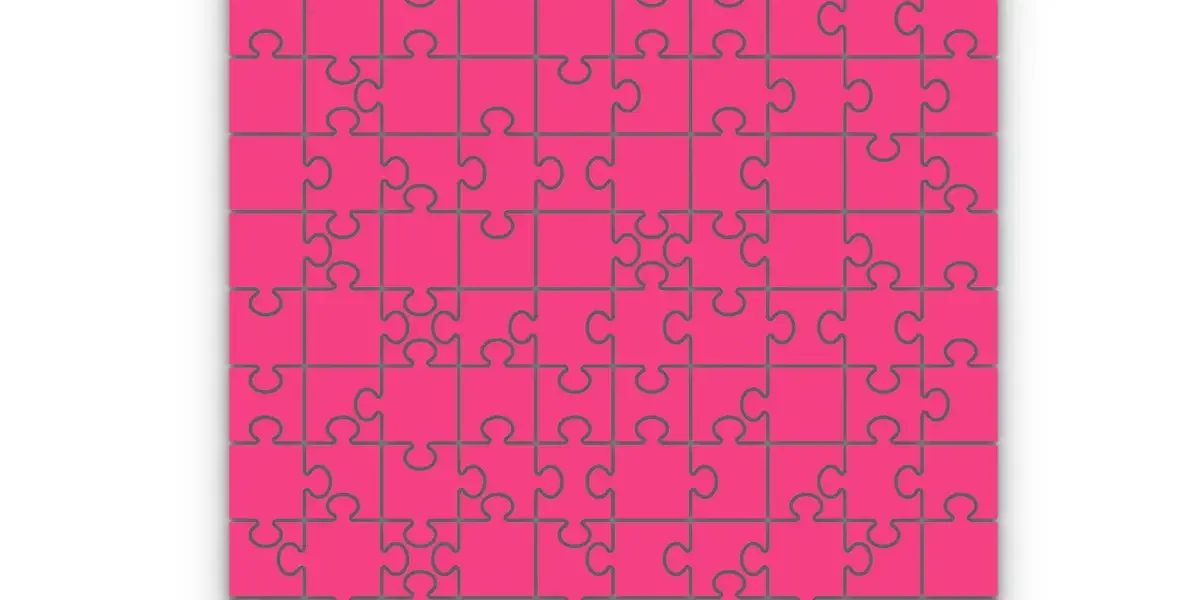
Interlocking puzzle-piece modules that can only connect one way. Grasshopper file for download.
Table of contents
1. Introduction
1.1 What is Monoceros
Monoceros is a legendary animal living in the huge mountains in the interior of India. It has the body of a horse, the head of a stag, the feet of an elephant and the tail of a boar.
Monoceros is also a suite of tools for arranging discrete Modules in an Envelope according to user-defined connection Rules. Wave Function Collapse searches for arrangements that satisfy those encoded constraints. It does not optimise an architectural objective or establish performance beyond the supplied Rules. Monoceros is a plug-in for Rhino / Grasshopper originally created at studio Subdigital by Ján Tóth and Ján Pernecký in 2021; Monoceros 3 is developed and maintained by Ján Pernecký.
Monoceros 3 introduces a significant set of capabilities over the original release:
- Weighted Observation and weighted Entropy - per-Module probability control lets the user bias the Solver toward or away from specific Modules in each Slot.
- Heterogeneous Slot dimensions - Cells of different X, Y, Z sizes can coexist in the same Envelope, enabling mixed-scale assemblies.
- Automatic Module Rotations - Rotational Freedom on Construct Module lets Construct Assembly generate up to 24 permitted orientations per Module. Module Rotations generates explicit variants, with voxel-based deduplication.
- Voxel engine for Connector and Rule suggestion - robust Face-matching even for complex or irregular geometry.
- Multi-solution output - multiple solve results from different Random Seeds can be collected in a single pass.
- Parallel solving - the first Attempt runs alone; further Attempts run in parallel on available CPU cores with incrementing Random Seeds when it is not fully solved or when Return first is False, provided Max Attempts is greater than 1. Results can be fully solved or partial.
- Multi-cell Modules - give Construct Module several adjacent Cells and it occupies them all, placed as one rigid body, for design elements larger than a single Slot.
- Full Grasshopper integration - all Monoceros types cast to and from standard Grasshopper types, allowing direct connection to any GH component.
1.2 What is Wave Function Collapse
Wave Function Collapse (WFC) fills an entire spatial Envelope with Modules according to a set of adjacency Rules. The Envelope is divided into discrete, box-shaped Slots. Each Slot starts out with a list of all Modules that are allowed to occupy it. The algorithm progressively narrows those lists, Slot by Slot. In a complete result every Slot holds exactly one Module and every pair of neighboring Modules is permitted by the Rules.
The WFC Solver propagates constraints across the Envelope and observes individual Slots. A complete result has exactly one Module candidate in every Slot and satisfies the encoded adjacency Rules. Monoceros 3 can also return a partial Assembly when an Attempt stops at its Observation limit: unresolved Slots still contain multiple candidates. A Contradictory Attempt has at least one Slot with no candidate. The Assemblies list contains non-Contradictory complete or partial results; if every Attempt contradicts, it contains one Contradictory Assembly. Inspect the Report, Deterministic and Contradictory outputs before materialising a result. A partial Assembly can be passed to another WFC Solver to continue solving. These statuses describe the encoded Assembly, not circulation, accessibility, structural or fabrication compliance.
Monoceros is a loose implementation of the Wave Function Collapse algorithm originally developed for game design by Maxim Gumin and extended and promoted by Oskar Stålberg with his game Townscaper. For an accessible visual explanation see Oskar Stålberg's EPC2018 talk; for the theoretical background see Constraint Satisfaction Problems on Wikipedia.
The algorithm
WFC proceeds in four phases:
- Canonicalization – Before the first Observation, the Solver runs an initial Propagation pass on the starting state. This removes any Module that is already impossible in a Slot given the initial allowed-Module lists and Rules, reducing every Slot to the tightest consistent set of possibilities. The result is the Canonical starting state. If any Slot reaches zero allowed Modules during Canonicalization, the setup is Contradictory and no solving is attempted.
- Observation – The highest Slot Priority is selected first. Among Slots at that priority, the Slot with the lowest Entropy is selected, with random tie-breaking, and assigned a Module chosen according to its per-Slot Weights. A Slot that has only one remaining allowed Module becomes Deterministic without randomness.
- Propagation – The newly fixed assignment is propagated outward through the grid. For each neighbor of the observed Slot, any Module that can no longer legally occupy that Slot - because the Rules no longer permit it next to the now-fixed neighbor - is removed from its allowed list. This removal can in turn force further removals in the neighbors’ neighbors, cascading recursively until the grid reaches a stable state with no further removals possible.
- Repeat – Steps 2 and 3 alternate until either all Slots are Deterministic (success) or a Slot reaches zero allowed Modules (a Contradictory state). The first Attempt uses the given Random Seed on one thread. If it does not fully solve, or if Return first is False, further Attempts run in parallel with incrementing Seeds, up to Max Attempts.
1.3 What are the design principles of Monoceros 3?
Monoceros 3 is not a sequential update of Monoceros 1 but a redesigned tool built on three core principles:
- Less Monoceros, more Grasshopper - what can be done with vanilla Grasshopper should be. Monoceros data types connect directly to standard Grasshopper components and other plug-ins.
- The tool is not the workflow - no design strategy is enforced by the tool. Monoceros components combine freely with any Grasshopper workflow.
- Explicit by default - every decision is visible in the Grasshopper canvas.
These principles caused substantial changes from Monoceros 1. Monoceros 3 data types and components are not compatible with Monoceros 1.
1.4 How do I migrate from Monoceros 1?
Monoceros 3 is a substantial redesign, not a feature update. Data types and components are not compatible with Monoceros 1. The most impactful improvements for daily workflow are:
- Weighted Observation - each Module in each Slot can carry its own Weight. Higher Weight increases the probability of being chosen during Observation, enabling gradient effects, frequency control, and partial pre-determination - none of which were possible in Monoceros 1.
- Heterogeneous Slot dimensions - the Envelope can mix Cells of different sizes in a single solve. Monoceros 1 required all Cells to be identical. Mixed-scale assemblies are now straightforward.
- Module Rotations component - Rotational Freedom on Construct Module lets Construct Assembly expand permitted variants; Module Rotations generates up to 24 explicit variants for a fully rotatable Module, with voxel-based deduplication. In Monoceros 1, every rotated variant had to be defined by hand.
- Multi-solution parallel solving - set Return first to False to run further Attempts in parallel and receive an Assembly for each non-Contradictory result on the Assemblies list output. Results can be fully solved or partial; if all Attempts contradict, the output contains one Contradictory Assembly.
- Voxel engine for Rule suggestion - Detect Rules From Voxels matches Face layers by voxel pattern rather than raw geometry, including complex or irregular Module Faces.
- Full Grasshopper type integration - all Monoceros types cast to and from standard Grasshopper geometry. A Slot casts to a Cell, Box, Brep, Point, or Plane. Monoceros components connect directly to standard GH tools without manual conversion steps.
- Indifference as an Assembly-level setting - the Indifference toggle on Construct Assembly replaces the Indifferent Rule from Monoceros 1. The effect is identical but the setup is cleaner and entirely explicit.
2. How is Monoceros structured?
2.1 What is the Monoceros workflow?
A typical Monoceros 3 workflow follows these steps:
- Define a Grid - Use the Homogeneous Grid or Heterogeneous Grid component to create Cells. A Cell carries only geometry - its size and position. A collection of Cells forms a grid. It is important to understand that Cells and Slots can be placed freely in world space; nothing enforces that they form a valid grid. Using the grid construction components guarantees a correct arrangement; any manually assembled or post-processed set of Cells must be carefully verified.
- Construct Modules - Define each Module with one or more Face-connected Cells and optional geometry. Module Name may be left empty for a generated name. Set Rotational Freedom on Construct Module to allow rotation variants in Construct Assembly; Module Rotations generates explicit variants.
- Analyze Faces - Extract and inspect the six Faces of each Module. Use the Detect Rules From Geometry or Detect Rules From Voxels components to identify matching Face pairs.
- Define Rules - Create Rules specifying which Face pairs are allowed to touch. Each Rule connects a source Face to a target Face facing the opposite Direction.
- Construct Slots (Envelope) - Create Slots from Cells, optionally specifying which Modules are allowed in each Slot and their relative Weights. This step converts the Cells into an Envelope: Cells carry only geometry; Slots additionally carry the list of allowed Module candidates and per-Module Weights needed for solving. If the Allowed Module Names input is not connected, the Slot is created as allow-all and Construct Assembly resolves it to the authored Module Names whose Cells fit that Slot's Cell size.
- Add Boundary - Optionally add boundary Cells and Slots, or use Require Terminators and Terminators on Construct Assembly to restrict which Modules may fill exposed Slot Faces on non-flat Axes without adding Cells.
- Construct Assembly - Feed Modules, Slots, optional Slot Priorities, allowed, disallowed and exclusive Rules and Connector Pairs, Connectors, and optional Terminators into Construct Assembly. Set Indifference, Clean up, Remove Unused Connectors and Require Terminators as needed. The component expands rotations, applies the constraints, audits, and packages a Discrete Assembly.
- Solve - Connect the Assembly to the WFC Solver. Assembly is the sole design-data input. The Assemblies list output can contain fully solved or partial Assemblies; if all Attempts contradict, it contains one Contradictory Assembly. To place Modules step by step instead, connect the Assembly to the Growth Solver; it returns one grown Assembly.
- Materialize - Connect the solved Assembly to the Materialize Assembly component to extract placed geometry.
2.2 Where are the Monoceros components in Grasshopper?
All Monoceros 3 components live in the Monoceros 3 tab in the Grasshopper ribbon. They are organized into seven subcategories:
- Main - Construct Assembly, Deconstruct Assembly, Dissolve Assembly, WFC Solver, Growth Solver, Materialize Assembly, Audit Assembly, Sample Geometry
- Connector - Connector construction, identification, pairing, suggestion, preview, and Terminators
- Envelope - Grid creation, boundary, topology, geometry slicing
- Module - Module construction (single- and multi-Cell), deconstruction, rotations, deduplication
- Face - Face extraction, analysis, comparison, grouping, preview
- Rule - Rule construction, deconstruction, detection, preview
- Slot - Slot construction, deconstruction, change and occurrence counting, pattern finding, preview, materialization
3. What data types does Monoceros use?
Monoceros 3 defines custom Grasshopper data types for all elements used in a WFC workflow. All Monoceros types can be passed through standard Grasshopper wires. Several support viewport preview and baking.
3.1 Grid
 3.1.1 Cell
A Cell is the basic spatial Cell unit of a Monoceros grid - a box-shaped region that defines the size and position of one Cell. Multiple Cells form a grid; when converted to Slots via the Construct Slot component, they form an Envelope.
Cells are created by Homogeneous Grid, Heterogeneous Grid, Cells From Geometry, or Add Boundary Layer. They can also be cast from a Box, BoundingBox, Rectangle, box-shaped Brep, Module, or Slot. A Cell exposes its Box geometry, from which center, dimensions, and Orientation can be derived.
Validity
A Cell is valid when its Box geometry is non-degenerate - all three dimensions greater than zero. Invalid Cells are rejected by all Monoceros components with a warning.
Viewport preview
Draws a slightly shrunken wireframe box with short colored lines pointing outward from the centers of the +X, +Y, and +Z Faces. Degenerate Cells draw in red.
Casting
| From / To | Type | Notes |
|---|---|---|
| Cast from | Box |
A Rhino Box is wrapped directly into a Cell. |
| Cast from | BoundingBox |
A BoundingBox is wrapped directly into a Cell. |
| Cast from | Rectangle |
Forms a box centered on the rectangle plane, with thickness equal to the smaller side length. |
| Cast from | Brep |
Accepts only a box-shaped Brep whose volume matches its bounding box or an oriented box formed by eight vertices. |
| Cast from | Module |
Returns its anchor Cell. |
| Cast from | Slot |
Returns its Cell. |
| Cast to | Box |
Returns the Cell as Rhino Box geometry. |
| Cast to | Brep |
Returns the Cell as a closed Brep surface. |
| Cast to | Point |
Returns the center point of the Cell. |
| Cast to | Plane |
Returns the center plane of the Cell with its Orientation. |
| Cast to | Vector |
Returns the diagonal vector (X, Y, Z dimensions) of the Cell. |
String representation
Displays Cell: Center {x,y,z}, Dimensions {x,y,z}, Axes: X {..}, Y {..}, Z {..}. A degenerate Cell reports the box is degenerate.
Baking
Cells do not bake directly. Cast a Cell to Box or Brep to bake its geometry.
3.2 Module
 3.2.1 Module
A Module is the fundamental design element in Monoceros 3. It carries a name, optional geometry, and one or more Face-connected Cells. The first Cell is its anchor. Each Cell has six Faces; only external Faces take Rules or Connectors. A single-Cell Module addresses them as +X through -Z; a Multi-cell Module adds a Cell ordinal, such as +X0. These Faces determine which neighboring Modules may legally be placed adjacent to it.
During WFC solving, each Slot starts with the full list of allowed Modules as candidates. The Solver progressively eliminates candidates - removing any Module from a Slot when its presence would violate a Rule with a neighboring Slot - until each Slot holds exactly one Module (Deterministic) or none (Contradictory). Selection is probabilistic and guided by the per-Module Weights stored in each Slot.
The Module’s geometry does not need to fit exactly inside the Cell - it can extend beyond or remain smaller. When geometry fits tightly and aligns with the Faces, Faces can be suggested automatically using the Detect Rules From Geometry or Detect Rules From Voxels components.
Key properties
- Module Name - A unique, lowercase string. Names are trimmed and lowercased automatically on input. Construct Module generates a name when this input is empty. Only Module Rotations variants of one source Module may share a name; other repeated names are an Error.
- Cells - One or more Face-connected Cells. The first is the anchor Cell; Deconstruct Module also reports the Footprint and Cell Count.
- Geometry - Optional Rhino geometry (curves, surfaces, Breps, meshes). Can exceed the bounding box.
- Faces - Six per Cell, with external Faces addressable by Direction and, for Multi-cell Modules, Cell ordinal. Faces without a Rule are treated as Indifferent when indifference is enabled on Construct Assembly.
- Rotational Freedom - None, X only, Y only, Z only, or Full. Construct Assembly expands permitted variants; Dissolve Assembly returns the Solver-level Modules including those variants.
Viewport preview
The Module preview draws:
- The Module geometry (wireframe for curves; shaded for Breps and Meshes), mirroring Rhino’s own display logic: shaded-style display modes show the source objects’ original display colors, and rendered-style modes show their assigned render materials including bitmap and transparency textures. Wireframe-style display modes draw only the edges, never shaded geometry. Selection highlighting (green for selected, red for invalid) is drawn on the wireframe edges only, so the realistic surface colors stay visible while selecting.
- A semi-transparent teal Cell outline when valid, red when invalid. Multi-cell Modules draw each footprint edge once, solid on the outside and dotted at inner seams.
- An outward arrow and address at each external Face, colored by Axis: X = red, Y = green, Z = blue. Face address text appears when its Face spans at least 450 pixels on screen.
- Arc arrows around each allowed rotation Axis and the Module Name as 3D text on three orthogonal planes. The name is teal when valid and red when invalid, and appears when the footprint spans at least 450 pixels on screen.
Validity
A Module is valid when its name, pivot plane, footprint, and six Faces per Cell are valid and its Cells form one Face-connected block. Corner or edge contact alone is insufficient. Modules with no geometry participate in solving but produce no materialized geometry. Its string representation starts Module "name" with 2 geometries in Cell: Center ... for a Module with two geometry items; it includes a rotation label when set and an invalidity reason when invalid.
Casting
| From / To | Type | Notes |
|---|---|---|
| Cast from | (none) | Use the Construct Module component. |
| Cast to | Module Name |
Extracts the Module's name as a Module Name value. |
| Cast to | Cell |
Extracts the anchor Cell of a valid Module. |
| Cast to | Point |
Returns the center point of the anchor Cell. |
| Cast to | Plane |
Returns the center plane of the anchor Cell with its Orientation. |
| Cast to | Vector |
Returns the diagonal vector (X, Y, Z) of the anchor Cell. |
Baking
Modules with geometry bake as one block instance at the identity transform, retaining captured per-object attributes. A Module without geometry bakes nothing.
 3.2.2 Module Name
A Module Name is a lowercase string identifier passed to the WFC Solver to represent a Module type. Input strings are converted to lowercase automatically.
Module Names identify authored Modules. Construct Assembly rejects separately authored Modules with the same name, even when their Cells have different dimensions. Only rotation variants of one source Module from Module Rotations may share a name; Construct Assembly merges them into one Module with those orientations. In a Heterogeneous Grid, give Modules with different Cell sizes distinct names and define their Rules separately.
Rules apply to rotation variants. A Rule defined for a Module Name is expanded to its allowed rotations during Construct Assembly.
Naming Modules of different sizes. Modules of different Cell sizes need distinct names, even when they have the same connection Rules. Define Rules for each named Module. See example 2.11 - Naming Modules of different sizes for a detailed worked example.
Validity
A Module Name is valid when it is non-empty and free of the reserved characters : (colon), -> (arrow), @, #, and newlines. Spaces are allowed.
Casting
| From / To | Type | Notes |
|---|---|---|
| Cast from | String |
The string is trimmed and lowercased before use as the Module Name. |
| Cast from | Module |
Extracts the Module's name. |
| Cast from | Integer |
Prefixes the integer with module-, for example module-3. |
| Cast from | Number |
Prefixes the number with module-. |
| Cast from | Data Path |
Prefixes the path with module-, for example {0;1} becomes module-0-1. |
| Cast to | String |
Returns the name string. |
String representation
Returns the name string, for example: wall or corner-piece.
Baking
Module Names are string values and do not bake directly.
3.3 Face
 3.3.1 Face Index
A Face Index identifies one of six Face Directions, numbered 0–5. Each index maps to a named Direction combining an Axis (X, Y, or Z) and an Orientation (positive or negative). Opposite Face Indices differ by 3 (+X 0 ↔ -X 3, etc.).
Face Indices appear on the Audit Assembly outputs Terminator Faces Covered and Terminator Faces Missing, and as the Face part of Face, Rule, and Connector strings. Get Module Faces and Construct Rules From Faces use Faces.
| Index | Name | From / To | Opposite |
|---|---|---|---|
0 |
+X |
X Positive | -X (3) |
1 |
+Y |
Y Positive | -Y (4) |
2 |
+Z |
Z Positive | -Z (5) |
3 |
-X |
X Negative | +X (0) |
4 |
-Y |
Y Negative | +Y (1) |
5 |
-Z |
Z Negative | +Z (2) |
Casting
| From / To | Type | Notes |
|---|---|---|
| Cast from | Integer |
Integers 0–5 map directly to Faces. |
| Cast from | Number |
Numbers are truncated to integers 0–5. |
| Cast from | String |
Accepts numeric ("0"), named ("+X", "-Y"), unsigned or lowercase Axis letters, and a Cell ordinal such as "+X12". |
| Cast to | Integer |
Returns the numeric index (0–5). |
| Cast to | Number |
Returns the numeric index. |
| Cast to | String |
Returns the named Direction, with a Cell ordinal when present. |
Validity
Valid indices are integers 0 through 5. Named strings may include a Cell ordinal for Multi-cell Modules; X and y mean positive X and Y.
Baking
Face Indices do not bake directly.
 3.3.2 Face (UID)
A Face uniquely identifies a specific Face on a specific Module. It combines a Module Name and a Face Index.
Properties
- Module Name - The name of the Module this Face belongs to.
- Face Index - The Face Direction as an integer (0-5) or named form (
+X…-Z), with a Cell ordinal on Multi-cell Modules.
String representation
Format: modulename:+X, or modulename:+X0 for a Multi-cell Module. A Module supplied to a Face or Module input represents all its Faces as the wildcard modulename:*. Both numeric and named indices are accepted. Examples:
wall:+X
corner:3
In Rules the format is:
wall:+X -> corner:-XValidity
A FaceId is valid when its Module Name is non-empty, contains no reserved characters, and its Face Index is in the range 0–5.
Casting
| From / To | Type | Notes |
|---|---|---|
| Cast from | String |
Parses the "modulename:faceindex" format. |
| Cast from | Module |
Represents all Faces of that Module as a wildcard, expanded by a Face or Module input. |
| Cast to | String |
Returns the FaceId string, e.g. wall:+X. |
Baking
Face UIDs do not bake directly. Use the Preview Faces component to visualize them in the viewport.
3.4 Slot
 3.4.1 Slot
A Slot represents one Cell in the Envelope. It holds the list of Module Names currently allowed to occupy it, along with a per-Module Weight for each candidate. The WFC Solver progressively reduces this list until each Slot holds exactly one Module (Deterministic) or none (Contradictory). Before solving, most Slots allow multiple Modules and are therefore Non-deterministic.
Key properties
- Box - The Cell bounding box (same geometry as the Cell it was created from).
- Allowed Module Names - The list of Module Names still allowed in this Slot.
- Module Weights - One Number per allowed Module, stored only on the Slot. Higher Weight increases the probability of selection. Missing Weights default to
1.0; a shorter list repeats its last value. A Weight of zero or less removes that Module from the Slot. A Weight covers all rotated variants of the Module. - Total Modules Count - Set by Construct Assembly to the number of unique Module Names across the Envelope. Before Assembly construction it is zero, and the preview shows the allowed count with the white end of the gradient.
- Allows All - True when the Slot was constructed without explicit Module Names (empty allowed list and zero Total Modules Count). An allow-all Slot is neither Deterministic nor Contradictory; Construct Assembly resolves it to the authored Module Names whose Cells fit the Slot's Cell size.
States
The Solver aims to make every Slot Deterministic. Slots can also become Deterministic before solving when their allowed list is restricted manually - for example by constructing a Slot with only one allowed Module Name.
| State | Allowed count | Preview color | Meaning |
|---|---|---|---|
| Contradictory | 0 | Red | No Module fits - this solve Attempt failed. The Solver will retry with a different Seed. |
| Deterministic | 1 | Green | Exactly one Module is assigned. The Slot is solved and can be materialized. |
| Non-deterministic | 2+ | Gradient from black (2 allowed) to white (all allowed) | Multiple Modules are still possible - not yet solved. |
| Allow-all | 0 (empty list, zero Total) | White | Unresolved: created without explicit Module Names. Construct Assembly resolves it to the authored Module Names whose Cells fit the Slot's Cell size. Previews with the label All. |
Viewport preview
Draws a colored wireframe box. The wireframe is intentionally drawn slightly smaller than the actual Cell. Adjacent Slots share Faces, so if the Cells were drawn full-size their edges would coincide and overlap, making individual Cells impossible to distinguish in the viewport. Shrinking each box inward by a small factor ensures there is always a visual gap between neighbors, even at zero distance. The actual solving geometry uses the full Cell.
The occupancy label is drawn on three Faces (XY, XZ, YZ) once the Slot spans at least 450 pixels on screen. It shows the Module Name for a Deterministic Slot, (-) for a Contradictory Slot, All for allow-all, N / Total after Construct Assembly, or N before it. Colored Direction lines start at the positive X, Y, and Z Face centers.
Weight bar chart. When a Slot carries non-uniform Module Weights and is zoomed in close enough to span 750 pixels on screen (a single Slot dominating the view), a bar chart is drawn above the occupancy label on the top (XY) Face: one narrow wireframe rectangle per allowed Module, in allowed-Modules order, captioned with the Weight (two decimals) and the Module Name written vertically beside the bar. Bar heights are normalized so the largest Weight spans half the Face; a dotted ceiling line marks the normalization maximum. Captions shrink with the Module count and are skipped when unreadable, so very high Module counts drop captions automatically. Slots with uniform (default) Weights draw no chart.
String representation
Displays state and Cell geometry, for example: Slot allows 3 Modules in Cell: Center ..., Slot allows Module "wall" in Cell: Center ..., Slot allows no Modules in Cell: Center ..., or Slot [All allowed] at Cell: Center .... Each ends with a period; invalid Slots are prefixed by the invalidity reason.
Casting
Slots automatically cast to Cell when passed to components that accept Cells (such as Add Boundary Layer). This means solved Slots can be used directly wherever Cells are expected.
| From / To | Type | Notes |
|---|---|---|
| Cast from | (none) | Use the Construct Slot component. |
| Cast to | Cell |
Returns the Slot's Cell, enabling use wherever Cells are expected. |
| Cast to | Box |
Returns the Slot's Cell as Rhino Box geometry. |
| Cast to | Brep |
Returns the Slot's Cell as a closed Brep surface. |
| Cast to | Point |
Returns the center point of the Slot's Cell. |
| Cast to | Plane |
Returns the center plane of the Slot's Cell. |
| Cast to | Vector |
Returns the diagonal vector (X, Y, Z) of the Slot's Cell. |
Baking
Slots bake as colored boxes reflecting their state.
3.5 Rule
 3.5.1 Rule
A Rule defines an allowed adjacency between two Module Faces. It holds two FaceIds - a source Face and a target Face - which typically Face opposite Directions (e.g. source Faces +X, target Faces -X). A non-opposing Rule (e.g. a:+X → b:+Y) is also accepted: it is a Connector-symmetry hint that Construct Assembly expands into opposing-Face Rules referencing rotation variants of the target Module (the Solver itself only ever consumes opposing-Face Rules). Rules are bidirectional for equality: wall:+X → corner:-X is equivalent to corner:-X → wall:+X, so each adjacency only needs to be defined once.
Validity
Both FaceIds must be individually valid. The source and target Directions do not have to be opposite - a non-opposing pair is a valid Connector-symmetry hint (see above). For full validation, the referenced Module Names must exist in the provided Module list.
String representation
Format: modulea:+X -> moduleb:-X
Casting
| From / To | Type | Notes |
|---|---|---|
| Cast from | String |
Parses "module:index -> module:index"; if one Face Index is omitted, it uses the opposite of the given index. |
| Cast to | String |
Returns the Rule string, which can be parsed back into a Rule. |
Baking
Rules do not bake directly. Use the Preview Rule component to visualize them in the viewport.
3.6 Connector
 3.6.1 Connector
A Connector is a named, rotation-aware interface that binds a type identity to a specific Module Face. Connectors emulate physical Connectors (USB-A, USB-C, 3.5 mm jack): two Faces can connect only when they carry compatible Connectors. Each Connector combines a name, four symmetry flags, a Module Name, a Face Direction, and an in-plane rotation into a single object. There is no separate type-definition step - all Connectors sharing the same name are implicitly the same type. The name carries the type identity.
The four symmetry flags define which of the four in-plane rotations (0°, 90°, 180°, 270°) are self-identical. When all four flags are true, the Connector is rotationally invariant (like a round jack). When only some flags are true, the Connector distinguishes certain rotations from each other, which affects how Rules are generated for rotated Module variants.
Key properties
- Name - A lowercase string identifying the Connector type. All Connectors with the same name are the same type. Must not contain
:,->,@,#, or a newline. Spaces are allowed. - Symmetry 0° - Self-identical at 0° rotation. Default:
true. - Symmetry 90° - Self-identical at 90° rotation. Default:
false. - Symmetry 180° - Self-identical at 180° rotation. Default:
false. - Symmetry 270° - Self-identical at 270° rotation. Default:
false. - Module Name - The name of the Module this Connector is placed on.
- Face Direction - The Face Direction as a Face Index (
+X…-Z). - Rotation - In-plane rotation on the Face: 0, 90, 180, or 270 degrees.
String representation
Format: connectorName#rot-A@moduleName:faceIndex. The rotation segment is optional on input and defaults to zero; the Face Index may include a Cell ordinal, such as wall:+X0. A String input sets all four symmetry flags to true. Example: usba#rot-0@wall:+X.
Validity
A Connector is valid when its name is non-empty, contains no reserved characters (:, ->, @, #), at least one symmetry flag is true, the Module Name is valid, the Face Direction is valid, and the rotation is one of 0, 90, 180, or 270.
Casting
| From / To | Type | Notes |
|---|---|---|
| Cast from | String |
Parses "connectorName#rot-A@moduleName:faceIndex", with an optional rotation segment. |
| Cast to | String |
Returns the Connector string, which can be parsed back into a Connector. |
Preview & Baking
The Connector data type does not support viewport preview or baking on its own. Construct Connector, Connector From Point, Detect Connectors From Voxels, Match Connectors By Geometry, Match Connectors By Voxels, and Preview Connector draw Connector stickers on Module Faces. Preview Connector can also draw compatible-Face curves from Connector Pairs and bake its preview.
 3.6.2 Connector Pair
A Connector Pair declares that two Connector types can connect across opposing Faces. A Connector Pair stores two name strings (not references to Connector objects). Compatibility is bidirectional: declaring A → B also allows B → A.
String representation
Format: sourcename -> targetname. Example: usba -> usba.
Validity
A Connector Pair is valid when both its source name and target name are non-empty and contain no reserved characters.
Casting
| From / To | Type | Notes |
|---|---|---|
| Cast from | String |
Parses the "source -> target" format. |
| Cast to | (none) |
Baking
Connector Pairs do not bake directly.
 3.6.3 Connector Name
A Connector Name is a lowercase string that identifies a Connector type. All Connectors sharing the same name are the same type. Input strings are converted to lowercase and trimmed automatically.
Validity
A Connector Name is valid when it is non-empty and free of the reserved characters :, ->, @, #, and newlines. Spaces are allowed.
Casting
| From / To | Type | Notes |
|---|---|---|
| Cast from | String |
The string is lowercased and trimmed. Fails if the result contains reserved characters. |
| Cast from | Connector |
Extracts the Connector's name. |
| Cast to | String |
Returns the name string. |
String representation
Returns the name string, for example: usba or rj45.
Baking
Connector Names are string values and do not bake directly.
3.7 Assembly
 3.7.1 Assembly
A Discrete Assembly (or simply Assembly) contains authored Modules, Slots, Connectors, allowed, disallowed and exclusive Rules and Connector Pairs, Terminators, Indifference and Require Terminators settings, and an Audit report. Construct Assembly expands rotation variants, generates Connector Rules, removes disallowed Rules, enforces exclusive Rules and Connector Pairs, applies Indifference, and restricts which Modules may fill exposed Slot Faces on non-flat Axes when Require Terminators is enabled, without adding Cells.
The Solver requires an Assembly as its design-data input. Construct Assembly has already expanded rotations and applied Indifference. The Solver returns an Assemblies list with fully solved or partial results; if all Attempts contradict, it returns one Contradictory Assembly.
Key properties
- Modules - Expanded, deduplicated list of all Modules including rotation variants.
- Slots - Current Slot states (pre-solve or post-solve).
- Rules - Complete merged Rule set (explicit, Connector-generated, rotation-expanded, and optionally Indifferent).
- Audit Result - Comprehensive validation report including grid validity, uncovered Faces, unknown Modules, over-constraint detection, and more.
String representation
Format: Assembly (N modules, M slots, K rules).
Validity
An Assembly is invalid if its build is incomplete or if Module Faces have neither Rules nor Indifference Rules. Construct Assembly reports build problems; Audit Assembly identifies uncovered Faces.
Casting
| From / To | Type | Notes |
|---|---|---|
| Cast from | (none) | Use the Construct Assembly component or the Solver's Assemblies output. |
| Cast to | (none) |
Baking
Assemblies Preview Rule adjacency curves, authored Module geometry and Slots, Terminator badges on terminated Faces and authored Slots referencing terminated Modules, and red X badges on authored Faces without a Rule or Connector. Assemblies do not bake directly; Construct Assembly can bake its Rule preview curves. Deconstruct Assembly returns authored inputs, while Dissolve Assembly returns Solver-level Modules including rotation variants, Slots, Explicit Rules and Indifferent Rules. Connect a solved Assembly to Materialize Assembly to produce geometry.
4. What Grasshopper components does Monoceros provide?
4.1 Connector
 4.1.1 Connector from Point
Create Connectors by pointing at a Module Face in the viewport. Combines Face-from-Point lookup with Connector construction: looks up every Module Face whose geometry contains the provided point and produces one Connector per match. Useful when authoring Connectors by clicking on Module Faces directly in the Rhino viewport. 8 inputs total.
Behavior
Resolves the Point Tag into one or more Module Faces using the same point-in-Face matching logic as Faces from Point, then constructs a Connector for each matching Face using the same name, rotation and symmetry inputs as Construct Connector. Connector Name is optional; when it is not wired, a Deterministic name with the prefix c- and four letters is generated and reported in a Remark. Only external Faces are matched; on a Multi-cell Module each matching Face is addressed to its own Cell. Zero matches raise a Warning (“Point does not match any Module Face.”); multiple matches emit an informational Remark listing how many Connectors were created. An unmatched Point Tag is also marked directly in the viewport with a red circle-and-cross badge laid flat in the world XY plane at the point, sized from the average provided Module size. Viewport preview draws the Connector sticker on every matched Face, identically to Construct Connector.
Inputs
| Name | Nickname | Type | Access | Description |
|---|---|---|---|---|
| Connector Name | CN | Connector Name | Item | Connector type name. Cast from string. If not provided, a Deterministic name is auto-generated from the component instance. (Optional) |
| Modules | M | Module | List | All available Modules to search for a Face hit. Only external Faces participate in point matching. Provide a flattened list. |
| Point Tag | Pt | Point | Item | Point marking a location on a Module Face. The component returns one Connector per Module Face whose geometry contains the point. |
| Face Rotation | R | Integer | Item | In-plane rotation of the Connector. 0 = 0°, 1 = 90°, 2 = 180°, 3 = 270°. Default: 0. |
| Symmetry 0° | S0 | Boolean | Item | Self-identical at 0° rotation. Default: true. |
| Symmetry 90° | S90 | Boolean | Item | Self-identical at 90° rotation. Default: false. |
| Symmetry 180° | S180 | Boolean | Item | Self-identical at 180° rotation. Default: false. |
| Symmetry 270° | S270 | Boolean | Item | Self-identical at 270° rotation. Default: false. |
Outputs
 4.1.2 Construct Connector
Create Monoceros 3 Connectors from Faces - named, rotation-aware interfaces placed on specific Module Faces. Combines type identity (name + symmetry) and placement (FaceId + rotation) in a single object. All Connectors sharing the same name are implicitly the same type. A Module wired directly into the Face input is cast to a short-lived wildcard FaceId that the component expands into the Module's six explicit Faces, producing one Connector per Face. Output is flattened. 8 inputs total. For point-based placement, use Connector from Point.
Behavior
Connector Name is optional. When it is not wired, a Deterministic name with the prefix c- and four letters is generated per component instance and reported in a Remark; Construct Connector, Connector From Point and Detect Connectors From Voxels share this name namespace. A wired name must not be empty or contain a line break, :, ->, @ or #; names are lowercased. Validates the symmetry flags (at least one must be true), Module Name, Face Direction and Face Rotation. Face Rotation accepts 0-3 or 90, 180 and 270 degrees; other values produce an Error. Symmetry 0 degrees defaults to true, while Symmetry 90, 180 and 270 degrees default to false. Creation failures are collected into one Error. A Connector with all four symmetry flags set to true behaves identically at every rotation - Rules generated for it do not distinguish Orientation. A Connector with selective flags (e.g. only 0° and 180°) produces different Rules for different in-plane orientations, enabling Direction-sensitive connections. When the optional Modules input is connected, the component draws a viewport preview showing the Connector as a label sticker on the target Face - displaying the Connector Name and symmetry arrows in the Connector’s type color, with degree labels (0°, 90°, 180°, 270°) indicating the in-plane rotation.
Inputs
| Name | Nickname | Type | Access | Description |
|---|---|---|---|---|
| Connector Name | CN | Connector Name | Item | Connector type name. Cast from string. If not provided, a Deterministic name is auto-generated from the component instance. (Optional) |
| Face or Module | F | Face ID | List | Face where the Connector is placed, obtained from the Get Module Faces component. A Module may be wired here instead, in which case it is expanded into all six of its Faces and one Connector is produced per Face. |
| Face Rotation | R | Integer | Item | In-plane current rotation of the Connector. 0 = 0°, 1 = 90°, 2 = 180°, 3 = 270°. Default: 0. |
| Symmetry 0° | S0 | Boolean | Item | Self-identical at 0° rotation. Default: true. |
| Symmetry 90° | S90 | Boolean | Item | Self-identical at 90° rotation. Default: false. |
| Symmetry 180° | S180 | Boolean | Item | Self-identical at 180° rotation. Default: false. |
| Symmetry 270° | S270 | Boolean | Item | Self-identical at 270° rotation. Default: false. |
| Modules | M | Module | List | Modules (optional). Modules for viewport preview. When connected, the Connector is displayed on the target Face. Provide a flattened list. |
Outputs
| Name | Nickname | Type | Access | Description |
|---|---|---|---|---|
| Connector | C | Connector | List | The constructed Connectors. |
 4.1.3 Construct Connector Pair
Declare which Connector types can connect across opposing Faces. Takes lists of Source Connector Names and Target Connector Names and produces a list of Connector Pairs. Compatibility is bidirectional - declaring A → B also allows B → A.
Behavior
Pairs every unique Source Connector Name with every unique Target Connector Name and outputs a flat list of Connector Pairs without duplicates. A Connector or text wired into either input is cast to its Connector Name.
Inputs
| Name | Nickname | Type | Access | Description |
|---|---|---|---|---|
| Source Connector Names | SCN | Connector Name | List | Connector Names defining the source side of each pair. |
| Target Connector Names | TCN | Connector Name | List | Connector Names defining the target side of each pair. |
Outputs
| Name | Nickname | Type | Access | Description |
|---|---|---|---|---|
| Connector Pairs | CP | Connector Pair | List | All cross-matched Connector Pairs, deduplicated. |
 4.1.4 Deconstruct Connector
Deconstruct a Connector into its constituent parts: Connector Name, Rotation in degrees (0, 90, 180 or 270), Module Name, and Face including any Cell ordinal. The inverse of Construct Connector.
Inputs
Outputs
| Name | Nickname | Type | Access | Description |
|---|---|---|---|---|
| Connector Name | CN | Connector Name | Item | The Connector type name. |
| Rotation | R | Integer | Item | The in-plane rotation in degrees (0, 90, 180, or 270). |
| Module Name | MN | Module Name | Item | The name of the Module this Connector is placed on. |
| Face | F | Face ID | Item | The Face identifier (Module Name and Face Index). |
 4.1.5 Construct Terminator
Create Terminators - boundary-facing markers placed on Module Faces. A Terminator declares that a specific Module Face is allowed to sit against the Envelope boundary when Require Terminators is enabled on Construct Assembly. For point-based placement, use Terminator from Point.
Behavior
The Face or Module input accepts either a Face (from the Get Module Faces component) or a whole Module. When a Module is wired, the component expands it into all six of its Faces and produces one Terminator per Face; a Remark reports how many were produced. This is the fastest way to mark an entire Module as fully boundary-compatible.
Terminators do nothing unless Require Terminators is enabled on Construct Assembly; supplying them when it is off produces a Warning. When enabled, Construct Assembly caps exposed Slot Faces on non-flat Axes: each needs a Module with a Terminator on the matching Face. The front and back Faces of a one-Cell-thick Envelope need no Terminators. If no allowed Module can cap a required Face, Construct Assembly reports a build problem and marks the Assembly invalid, so the WFC Solver refuses it. No extra boundary Cells are added - the grid stays exactly the Cells you authored.
The optional Modules input provides Modules for viewport preview. When connected, a Terminator badge - a smooth circle with an inner × - is drawn on each target Face in its Axis colour.
String representation
Format: Terminator@moduleName:faceIndex. Example: Terminator@pipe:+X.
A Terminator that targets one Cell of a Multi-cell Module spells that Cell's ordinal after the Face, as Terminator@pipe:+X1. The unnumbered form means the whole side: every Cell of the Module that exposes that Direction.
Inputs
| Name | Nickname | Type | Access | Description |
|---|---|---|---|---|
| Face or Module | F | Face ID | List | Face where the Terminator is placed, obtained from the Get Module Faces component. A Module may be wired here instead, in which case it is expanded into all six of its Faces and one Terminator is produced per Face. |
| Modules | M | Module | List | Modules (optional). Modules for viewport preview. When connected, the Terminator badge is displayed on the target Face. Provide a flattened list. |
Outputs
| Name | Nickname | Type | Access | Description |
|---|---|---|---|---|
| Terminator | T | Terminator | List | The constructed Terminators. |
 4.1.6 Detect Connectors from Voxels
Voxelize all Module Faces using Face-local ray scanning, group same-Direction Faces by matching voxel fingerprint (testing 4 rotations), assign a named Connector to each group with detected rotation offsets, and output Connector Pairs for groups whose fingerprints match across opposite-Direction Faces.
Behavior
Shoots rays from each Face plane in both Directions (inward and outward) on a uniform grid. The resulting 3D boolean fingerprint is compared across same-Direction Faces at four 90-degree rotations. Faces whose fingerprints match at any rotation form a Connector group and receive the same Connector Name with the detected rotation offset. Names come from the shared Connector auto-name table (c- followed by four letters), deterministically per component instance and uniquely across Connector components in the document; vox_N is used only when more groups are detected than names were reserved for this component. Symmetry flags are determined per group by testing the prototype fingerprint against itself at each rotation. Groups on opposite Directions are tested with a UV-mirrored comparison to account for the different coordinate frames of opposing Faces; each match produces a Connector Pair. The viewport shows Connector sticker previews (arrows and name labels) alongside voxel wireframes with a colour derived deterministically from each Connector Name, stable between recomputes. Bezier curves connecting compatible Module Faces are drawn for each detected Connector Pair, using the same visual language as Preview Rule.
Recompute limit. When the number of detected Connector groups changes between consecutive recomputes, the component schedules one additional solution pass to stabilize. This reschedule is capped at five consecutive Attempts; if the count keeps changing after five passes a Warning is shown and the current result is returned as-is.
Inputs
| Name | Nickname | Type | Access | Description |
|---|---|---|---|---|
| Modules | M | Module | List | Only external Faces are voxelized and analysed. Provide a flattened list. |
| Voxel Dimension | VD | Vector | Item | Number of voxels per Module Axis (X, Y, Z). Each component specifies how many voxels fit into the Module in the respective Direction. The Face grid resolution is derived from the two components that span the Face. |
| Precision | P | Integer | Item | Number of rays cast per Cell. Higher values detect smaller features with higher accuracy but reduce speed. |
| Inner Depth | ID | Number | Item | Scan depth inside the Cell as a fraction of the Module depth along the Face normal. 0.5 = half the Module depth, 1.0 = full depth. |
| Outer Depth | OD | Number | Item | Scan depth outside the Cell as a fraction of the Module depth along the Face normal. 0.0 = flush with the Face. |
Outputs
| Name | Nickname | Type | Access | Description |
|---|---|---|---|---|
| Connectors | C | Connector | List | One Connector per Module Face that has occupied voxels. Faces with matching geometry share the same Connector Name with detected rotation offsets. |
| Connector Pairs | CP | Connector Pair | List | Pairs of Connector Names whose voxel fingerprints match across opposite-Direction Faces. Feed into Construct Assembly. |
 4.1.7 Terminator from Point
Create Terminators from a point tag. Looks up every Module Face whose geometry contains the provided point and creates a Terminator for each matching Face in one step. Useful for authoring Terminators by clicking on Module Faces in the Rhino viewport. For Face-based placement, use Construct Terminator.
Behavior
Uses the same point-in-Face matching as Faces from Point: the component tests each external Face of every Module with a 0.01-model-unit tolerance. Each match addresses the Cell on which the Face lies, so a hit on a Multi-cell Module produces a numbered Face reference covering only that Cell. The input Modules also provide the viewport badge preview.
Zero matches raise a Warning and produce no Terminators. Multiple matches (e.g. two Modules whose geometries overlap at the point location) emit an informational Remark and produce one Terminator per match. Output is flattened.
Inputs
| Name | Nickname | Type | Access | Description |
|---|---|---|---|---|
| Modules | M | Module | List | All available Modules to search for a Face hit. Only external Faces participate in point matching. Provide a flattened list. |
| Point Tag | Pt | Point | Item | Point marking a location on a Module Face. The component returns one Terminator per Module Face whose geometry contains the point. |
Outputs
| Name | Nickname | Type | Access | Description |
|---|---|---|---|---|
| Terminators | T | Terminator | List | One Terminator per matched Face. If the Point marks multiple Faces (e.g. overlapping Modules), each match produces its own Terminator. |
 4.1.8 Match Connectors by Geometry
Given an exemplar Connector, find all geometrically matching Faces across all Modules and output Connectors with detected rotation offsets. Uses the same naked-edge / curve-endpoint / point extraction as Detect Rules From Geometry but additionally detects the in-plane rotation offset between each match and the exemplar.
Behavior
Extracts geometry from each input Module's external Faces, transforms it to a normalized base plane, and compares it against the exemplar Connector's Face. The exemplar Module and Face must be present among those external Faces; otherwise the component reports an error. For each match, it tests all four 90° rotations of the geometry pattern. Each output Rotation is the exemplar's Rotation plus the detected offset. The output covers matching Faces, including the exemplar itself, and inherits its name and symmetry flags. No matches produce a warning. Multiple exemplars may be wired in separate iterations; the viewport previews all their Connectors together as stickers on Module Faces.
Inputs
| Name | Nickname | Type | Access | Description |
|---|---|---|---|---|
| Exemplar | E | Connector | Item | The reference Connector whose Face geometry defines what to match. |
| Modules | M | Module | List | Only external Faces participate in geometry matching. Provide a flattened list. |
Outputs
| Name | Nickname | Type | Access | Description |
|---|---|---|---|---|
| Connectors | C | Connector | List | All matched Connectors with detected rotations. |
| Match Count | MC | Integer | Item | Number of Faces matched (including the exemplar). |
 4.1.9 Match Connectors by Voxels
Given a prototype Connector on a known Module, find all Faces across candidate Modules whose geometry matches the prototype’s Face. Uses Face-local bidirectional ray scanning to build voxel fingerprints and compares them at four rotations (0°, 90°, 180°, 270°).
Behavior
Shoots rays from each Face plane in both Directions (inward and outward) on a uniform grid. Intersection parity determines inside/outside state; intersection positions mark surface voxels. Candidate external Faces are first filtered by Face dimensions and voxel-grid dimensions, then their fingerprints are compared at all four 90° rotations. The output starts with a copy of the prototype Connector, followed by matches with its name and symmetry flags. The Modules input is optional: without it, only the prototype Connector is output. The prototype Module does not need to appear in the candidate Modules list. The prototype Face shows solid coloured voxels and white scan-bounds edges; candidate matches show wireframe voxel outlines with Axis colour coding.
Inputs
| Name | Nickname | Type | Access | Description |
|---|---|---|---|---|
| Prototype Connector | PC | Connector | Item | The reference Connector whose Face geometry defines what to match. Must belong to the Prototype Module. |
| Prototype Module | PMM | Module | Item | The Module that the Prototype Connector belongs to. Does not need to appear in the Modules list. |
| Modules | M | Module | List | Candidate Modules to search for Faces matching the prototype. Only external Faces are scanned. The prototype Module may or may not be included. |
| Voxel Dimension | VD | Vector | Item | Number of voxels per Module Axis (X, Y, Z). Each component specifies how many voxels fit into the Module in the respective Direction. The Face grid resolution is derived from the two components that span the Face. |
| Precision | P | Integer | Item | Number of rays cast per Cell. Higher values detect smaller features with higher accuracy but reduce speed. |
| Inner Depth | ID | Number | Item | Scan depth inside the Cell as a fraction of the Module depth along the Face normal. 0.5 = half the Module depth, 1.0 = full depth. |
| Outer Depth | OD | Number | Item | Scan depth outside the Cell as a fraction of the Module depth along the Face normal. 0.0 = flush with the Face. |
Outputs
| Name | Nickname | Type | Access | Description |
|---|---|---|---|---|
| Connectors | C | Connector | List | All matched Connectors including the prototype, with detected rotations. |
| Match Count | MC | Integer | Item | Number of Faces matched (including the prototype). |
 4.1.10 Preview Connector
Display Connectors on Modules as arrows and name labels. When Connector Pairs are also provided, bezier curves are drawn between compatible Module Faces. Display-only component (no geometry outputs). Supports baking of the bezier curves.
Behavior
Draws a Connector sticker (arrow and name label) on the assigned Face of each Module. Several Connectors on one Face are drawn; only exact repeats and per-Cell Connectors covered by a whole-side Connector in the same Direction are dropped. If any Connector references a Module absent from the Modules input, a Warning names it and nothing is drawn. When Connector Pairs are wired, the pairs are resolved to Rules internally and a bezier curve is drawn per Rule in the neutral grey used by Preview Rule. The bezier curves can be baked; Connector arrow/label geometry is not bakeable.
Inputs
| Name | Nickname | Type | Access | Description |
|---|---|---|---|---|
| Modules | M | Module | List | All Modules that the Connectors reference. Provide a flattened list. |
| Connectors | C | Connector | List | Connectors to display on their assigned Module Faces. |
| Connector Pairs | CP | Connector Pair | List | Optional. When provided, bezier curves are drawn between compatible Module Faces. |
4.2 Envelope
 4.2.1 Heterogeneous Grid
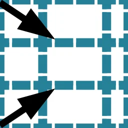
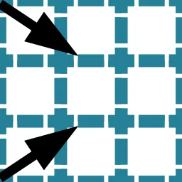
Generate a grid where Cells along each Axis can have different sizes. Each Axis receives an independent list of dimension values; the component creates all combinations. For example, three X sizes, four Y sizes, and two Z sizes produce 3×4×2 = 24 Cells, each with dimensions determined by its position along each Axis. The homogeneity of the Homogeneous Grid means all Cells are identical; here, each column, row, or layer has a distinct dimension while all Cells within the same column, row, or layer share that Axis value.
Behavior
Cells are placed with cumulative offsets along each Axis, starting with a Cell centered on the Base Plane origin. The resulting Cells can have different sizes in one, two, or all three dimensions. Each size list must be nonempty and contain only positive values; the grid cannot exceed 5,000,000 Cells.
What makes a grid Heterogeneous. The grid is only Heterogeneous when the size lists contain more than one distinct value along at least one Axis, so that neighbouring Slots end up with different dimensions. If all three lists contain a single repeated value, the result is identical to Homogeneous Grid. A grid is not Heterogeneous merely because its Cells are non-cubic - a Homogeneous Grid with Diagonal (2, 1, 3) already has rectangular Cells; every Cell is still the same size.
A practical way to create varied-size input lists is the Grasshopper Gene Pool component for interactively dragging individual values and seeing the resulting grid update in real time.
For the Heterogeneous Grid to work with WFC, Modules are required whose dimensions match the different Cell sizes. For example, if X sizes are [1, 2], you need at least one Module with X = 1 and one with X = 2. Give separately authored Modules distinct names and define Rules for each.
Naming Modules of different sizes. Construct Assembly rejects separately authored Modules with the same name, even when their sizes differ. Only rotation variants of one source Module may share a name. Use distinct names and Rules for different sizes. See example 2.11 - Naming Modules of different sizes for a detailed worked example.
The component flattens its Cells output in Z-fastest order, then Y, then X. Connect it directly to the Construct Slot component.
Inputs
| Name | Nickname | Type | Access | Description |
|---|---|---|---|---|
| Base Plane | P | Plane | Item | Grid Orientation and origin plane. |
| X Sizes | X | Number | List | Dimensions of grid Cells in the X Direction. |
| Y Sizes | Y | Number | List | Dimensions of grid Cells in the Y Direction. |
| Z Sizes | Z | Number | List | Dimensions of grid Cells in the Z Direction. |
Outputs
| Name | Nickname | Type | Access | Description |
|---|---|---|---|---|
| Cells | B | Cell | Tree | Heterogeneous Grid Cell instances with variable Cell sizes. |
 4.2.2 Homogeneous Grid
Generate a regular Envelope made of uniform Cells. All Cells share the same X, Y and Z dimensions, arranged in a cuboid block. This is the most common starting point for a WFC setup.
Behavior
Creates a 3D array of identically-sized Cells, aligned to the given base plane. Each individual Cell can have different X, Y, and Z dimensions; the homogeneity means all Cells in the grid share exactly those same dimensions. A single-Cell grid (X Count = Y Count = Z Count = 1) is valid and can be used for any purpose that requires an isolated Cell.
Non-cubic is not Heterogeneous. Setting the Diagonal to (2, 1, 3) produces rectangular Cells, but every Cell in the grid is still identical - the grid is still Homogeneous. You still need only one Module size. Use Heterogeneous Grid only when you need neighbouring Slots to have different sizes from each other. Although Cells do not need to be cubic, cubic Cells (X = Y = Z) are strongly recommended: non-cubic Cells constrain which Modules fit which Slots and can make the setup harder to manage.
The first Cell is centered on the Base Plane origin. The output is a data tree of Cells, flattened by the component with Z changing fastest, then Y, then X. The grid cannot exceed 5,000,000 Cells. Connect directly to the Construct Slot component.
Inputs
| Name | Nickname | Type | Access | Description |
|---|---|---|---|---|
| Base Plane | P | Plane | Item | Grid Orientation and origin plane. |
| Diagonal | D | Vector | Item | Grid Cell dimensions (width, depth, height). |
| X Count | X | Integer | Item | Number of grid Cells in the X Direction. |
| Y Count | Y | Integer | Item | Number of grid Cells in the Y Direction. |
| Z Count | Z | Integer | Item | Number of grid Cells in the Z Direction. |
Outputs
| Name | Nickname | Type | Access | Description |
|---|---|---|---|---|
| Cells | B | Cell | Tree | Homogeneous Grid Cell instances with uniform Cell sizes. |
 4.2.3 Add Boundary Layer
Surround an existing Grid or Envelope with one or more additional layers of Cells. Use this to control what appears at the outer edges of the Envelope - for example, to ensure open or closed boundary conditions, or to add a ring of dedicated “cap” Modules that frame the interior.
Behavior
Generates new Cells that are adjacent to - but not part of - the input Envelope. The component outputs only the new boundary Cells, not the original ones. The boundary Cells are typically converted to a separate set of Slots (using Construct Slot with different Module allowances than the interior), and only then merged with the interior Slots before passing all Slots to the WFC Solver.
The six directional toggles, Include +X, Include +Y, Include +Z, Include -X, Include -Y and Include -Z, default to true. For example, disable Include +Z (Z) to leave the top of the Envelope open. Diagonal Neighbors (D) defaults to false; when enabled, the layer also grows into diagonal Cells in the toggled 26-neighbourhood. Every empty neighbouring Cell is included, including holes enclosed inside the Envelope. When working with non-rectangular (masked) Envelopes, the boundary follows the actual shape rather than filling out to the bounding box, so each new layer can extend past the Envelope's original extent in every enabled Direction. Layers below 1 raise an Error. When all six Directions are disabled, a Warning is shown and no output is produced.
Inputs
| Name | Nickname | Type | Access | Description |
|---|---|---|---|---|
| Cells | B | Cell | List | All Cell objects to surround with boundary layers. |
| Diagonal Neighbors | D | Boolean | Item | Include diagonal Cell neighbors. |
| Layers | L | Integer | Item | Number of layers to add. |
| Include +X | X | Boolean | Item | Scan for boundary in positive X Direction |
| Include +Y | Y | Boolean | Item | Scan for boundary in positive Y Direction |
| Include +Z | Z | Boolean | Item | Scan for boundary in positive Z Direction |
| Include -X | -X | Boolean | Item | Scan for boundary in negative X Direction |
| Include -Y | -Y | Boolean | Item | Scan for boundary in negative Y Direction |
| Include -Z | -Z | Boolean | Item | Scan for boundary in negative Z Direction |
Outputs
 4.2.4 Are Cells Boundary
Identify which Cells in an Envelope border empty space, including interior holes. Returns a boolean per input Cell - true if the Cell is within the specified number of layers from an empty neighbour along an enabled Axis. Use this to separate boundary Cells from interior Cells to treat them differently - assign dedicated boundary Modules, restrict allowed candidates, or visualize the distinction.
Behavior
A Cell is a boundary Cell when at least one neighbour along an enabled Axis is empty. Include X, Include Y and Include Z each cover both Directions of that Axis. With Layers set to 1, Cells adjoining empty space are flagged; deeper layers flood inward through occupied Cells. With Layers at 0 or below, no Cell is flagged. When all three Axes are disabled, a Warning is shown and no output is produced.
The output boolean list matches the input list order one-to-one. A convenient workflow is to feed the boolean pattern into a Dispatch component to split the Cells (or their resulting Slots) into boundary and interior groups, then apply different constraints to each.
Inputs
| Name | Nickname | Type | Access | Description |
|---|---|---|---|---|
| Cells | B | Cell | List | All Cell objects to analyze. |
| Layers | L | Integer | Item | Number of outer layers to identify as boundary. |
| Include X | X | Boolean | Item | Scan for boundary in X Direction. |
| Include Y | Y | Boolean | Item | Scan for boundary in Y Direction. |
| Include Z | Z | Boolean | Item | Scan for boundary in Z Direction. |
Outputs
 4.2.5 Deconstruct Cell
Extract the center plane, diagonal dimensions and Axis intervals from a Cell. Useful for working with the geometry of individual Cells directly, for example to generate Module geometry at a Cell’s exact position and size.
Behavior
Decomposes each Cell in the input tree into its geometric components. Each output item is placed at the input path with the Cell's item index appended. If any Cell is null or invalid, one Error names every offending tree position and the component produces no output.
Inputs
Outputs
| Name | Nickname | Type | Access | Description |
|---|---|---|---|---|
| Center Plane | P | Plane | Tree | The plane at the center of the Cell with the box's Orientation. |
| Diagonal | D | Vector | Tree | Vector representing the X, Y, and Z dimensions of the Cell. |
| X Interval | X | Interval | Tree | The interval along the X Axis (centered at origin: -halfX to +halfX). |
| Y Interval | Y | Interval | Tree | The interval along the Y Axis (centered at origin: -halfY to +halfY). |
| Z Interval | Z | Interval | Tree | The interval along the Z Axis (centered at origin: -halfZ to +halfZ). |
 4.2.6 Grid Topology
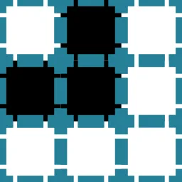
Extract the discrete grid coordinates and adjacency map of an Envelope. For each Cell, the component reports its integer position in the grid and which other Cells are its neighbors. Useful when reasoning about spatial relationships within the Envelope in Grasshopper - for example, to drive custom Module allowances based on grid position.
Behavior
The Relative Coordinates output gives each Cell’s integer (column, row, layer) position within the grid, expressed as a Point. These are not world-space coordinates - they are grid indices counted from the minimum corner of the grid's extent. Position (0, 0, 0) need not contain a Cell.
The Topology output is a tree where the input branch path with Cell index N appended contains the indices of Cell N's neighbors. By default, Diagonal Neighbors is false (Face neighbors only) and Bi-Directional Topology is true (neighbors in both Directions). Enabling Diagonal Neighbors includes edge and corner neighbors; disabling Bi-Directional Topology keeps only neighbors in the positive X, Y, and Z Directions.
Inputs
| Name | Nickname | Type | Access | Description |
|---|---|---|---|---|
| Cells | B | Cell | Tree | List of Cell items that define the grid layout. Provide a single flat list (one branch). |
| Diagonal Neighbors | D | Boolean | Item | Include diagonal neighbor boxes when computing topology (true/false). |
| Bi-Directional Topology | BiDi | Boolean | Item | When true, topology lists neighbors in both positive and negative Directions. When false, topology lists only neighbors in the positive Direction. |
Outputs
 4.2.7 Neighbor Cells
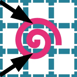
Find the Cells that are adjacent to a given set of focus Cells. Given Cell Indices, the component returns Neighbor Indices for Cells within the specified number of Layers along the enabled Axes. Useful for selecting “everything around” a particular sub-region of the Envelope.
Behavior
The search covers a box measured in grid steps along each enabled Axis, including diagonal neighbors. With Layers set to 1 and all Axes enabled, it can return up to 26 neighbors per focus Cell. Include X, Include Y, and Include Z restrict the search to the selected Axes. Focus Cells are excluded, and the output indices are unique and sorted in ascending order.
A typical workflow is to use the Are Cells Boundary component to get boundary indices, then feed those into Neighbor Cells to find the row of Cells just inside the boundary. You can then use a Dispatch component to separate Neighbor Cells from the rest and apply different Module allowances to each group.
Inputs
| Name | Nickname | Type | Access | Description |
|---|---|---|---|---|
| Cells | B | Cell | List | List of Cell objects representing the grid to analyze. Provide a flat list (flattened) of Cells. |
| Cell Indices | I | Integer | List | Indices of Cells for which neighbor indices should be computed. Provide indices relative to the supplied Cells list. |
| Layers | L | Integer | Item | Maximum search distance (in grid steps) to consider when collecting neighboring Cells. Defaults to 1. |
| Include X | X | Boolean | Item | Enable scanning for neighbors along the X Axis. |
| Include Y | Y | Boolean | Item | Enable scanning for neighbors along the Y Axis. |
| Include Z | Z | Boolean | Item | Enable scanning for neighbors along the Z Axis. |
Outputs
 4.2.8 Cells from Geometry
Generate a set of Cells whose Cells cover the shape of input geometry. Use this to define a non-rectangular Envelope that follows an arbitrary form - for example a curved building mass, a terrain surface, or a point cloud.
Behavior
The Populate Method input selects Surface Wrap, Fill Volume, or Surface Wrap + Fill Volume (the default). For Meshes, Surfaces, and Breps, Surface Wrap marks a Cell when the surface overlaps its box; Fill Volume marks a Cell when its centre lies inside a closed volume. Curves and Points are sampled. Interior Only keeps only Cells marked by Fill Volume but not Surface Wrap and skips Curve samples on a Cell Face.
A Mesh, Surface or Brep that does not enclose a volume (an open shell such as a box without a lid, a tube or a flat sheet) is never filled: it is voxelized by its surface only. Fill Volume and Surface Wrap + Fill Volume then give the same Cells as Surface Wrap, and Interior Only gives none. The component names such a shape in a remark. Closed solids are filled as usual.
Cells are aligned to the Base Plane and centred at integer multiples of the Cell Diagonal from its origin. Snapping to Cell boundaries uses the document tolerance, capped at 2% of a Cell; the component reports when it applies this cap.
Supported geometry types: Points, Curves, untrimmed Surfaces, Breps, and Meshes. Trimmed surfaces should be converted to Breps before use (use the Convert to Brep component in Grasshopper).
Inputs
| Name | Nickname | Type | Access | Description |
|---|---|---|---|---|
| Geometry | G | Geometry | List | Input Geometry. Geometry to populate with Cells. Supported types: Points, Curves, (untrimmed) Surfaces, Breps, Meshes. |
| Base Plane | B | Plane | Item | Grid space base plane. Defines Orientation of the grid. |
| Cell Diagonal | D | Vector | Item | Vector specifying the Cell size along base-plane-aligned X, Y and Z Axes. |
| Populate Method | F | Integer | Item | 0 = Surface Wrap 1 = Fill Volume 2 = Surface Wrap + Fill Volume Defaults to 2. |
| Interior Only | I | Boolean | Item | When enabled, a Mesh, Surface or Brep yields only the Fill Volume Cells that Surface Wrap does not mark: the Cells strictly inside the volume, regardless of Populate Method. Curve samples lying on a Cell Face are skipped. |
Outputs
4.3 Face
 4.3.1 Get Module Faces
Deconstruct a Module into its externally visible Faces, one list per Direction output.
Behavior
Reads the Module's externally visible Face set and outputs each Direction as a separate FaceId list. A single-Cell Module produces one FaceId per Direction (6 total), spelled +X..-Z. A Multi-cell Module may produce several per Direction - one per footprint Cell whose Face in that Direction is not covered by another Cell - numbered +X0, +X1, ... in spatial Cell order. Returns error if the Module is null or invalid. Also previews each Face directly on the Module in the viewport, using the same rectangle/arrow/Direction-label glyph as Preview Faces, so the outputs can be told apart by eye without wiring a separate preview component.
Inputs
| Name | Nickname | Type | Access | Description |
|---|---|---|---|---|
| Module | MM | Module | Item | A Module from which individual Faces will be extracted. For single-Cell Modules all 6 Faces are returned; for Multi-cell Modules only external Faces appear in the per-Direction outputs. |
Outputs
| Name | Nickname | Type | Access | Description |
|---|---|---|---|---|
| {GH_FaceIndex.XPositive} Face | {GH_FaceIndex.XPositive} | Face ID | List | Positive X Face. Face IDs for external Faces pointing in the positive X Direction. |
| {GH_FaceIndex.XNegative} Face | {GH_FaceIndex.XNegative} | Face ID | List | Negative X Face. Face IDs for external Faces pointing in the negative X Direction. |
| {GH_FaceIndex.YPositive} Face | {GH_FaceIndex.YPositive} | Face ID | List | Positive Y Face. Face IDs for external Faces pointing in the positive Y Direction. |
| {GH_FaceIndex.YNegative} Face | {GH_FaceIndex.YNegative} | Face ID | List | Negative Y Face. Face IDs for external Faces pointing in the negative Y Direction. |
| {GH_FaceIndex.ZPositive} Face | {GH_FaceIndex.ZPositive} | Face ID | List | Positive Z Face. Face IDs for external Faces pointing in the positive Z Direction. |
| {GH_FaceIndex.ZNegative} Face | {GH_FaceIndex.ZNegative} | Face ID | List | Negative Z Face. Face IDs for external Faces pointing in the negative Z Direction. |
 4.3.2 Analyze Face
Analyze Face properties including geometry, Direction and Rule/Connector usage. Provides Direction flags, Face planes, rectangles, and used/unused classification.
Behavior
Looks up each Face’s Module, extracts Face plane and rectangle geometry, determines Direction flags, and checks Rule and Connector references. A Module wired into Face or Module is expanded into its six Faces with a Remark. Faces naming an unknown Module or no external Face of their Module produce an Error and no output. Without Modules, a Warning says Face Planes and Rectangles could not be determined. Builds output trees parallel to the input Face tree.
Coverage is read per Cell, the same way Used Faces reads it. A reference that names a Cell ordinal, such as big:+X1, covers that one Cell’s Face; a reference without an ordinal, big:+X, covers the whole side - every Cell of the Module exposing that Direction.
Inputs
| Name | Nickname | Type | Access | Description |
|---|---|---|---|---|
| Face or Module | F | Face ID | Tree | Face to analyze, obtained from the Get Module Faces component or other Face-producing components. A Module wired here instead is expanded into all six of its Faces. |
| Modules | M | Module | List | Optional list of Module objects used to resolve Face geometry and planes. If omitted, some geometric outputs will be unavailable. Provide a flattened list. |
| Rules | R | Rule | Tree | Optional list of Rule objects used to determine Face usage patterns. When provided, outputs will indicate whether Faces are used by any Rule. |
| Connectors | C | Connector | Tree | Optional list of Connector objects used to determine Face usage patterns. A Face that has any Connector assigned to it is considered used. |
Outputs
| Name | Nickname | Type | Access | Description |
|---|---|---|---|---|
| Module Name | MN | Module Name | Tree | The Module Name associated with the analyzed Face (normalized to lowercase). |
| Face Planes | FP | Plane | Tree | Local planes describing the Face geometry when Module geometry is provided. |
| Face Rectangles | FR | Rectangle | Tree | Projected rectangle outlines of each Face when Module geometry is available. |
| Face Direction | FD | Vector | Tree | Unit vectors describing the Face normal in the Face base plane; returned as a tree parallel to Face Planes. |
| Is X | X | Boolean | Tree | True if the Face points in the X Direction of the Module. |
| Is Y | Y | Boolean | Tree | True if the Face points in the Y Direction of the Module. |
| Is Z | Z | Boolean | Tree | True if the Face points in the Z Direction of the Module. |
| Is -X | -X | Boolean | Tree | True if the Face points in the -X Direction of the Module. |
| Is -Y | -Y | Boolean | Tree | True if the Face points in the -Y Direction of the Module. |
| Is -Z | -Z | Boolean | Tree | True if the Face points in the -Z Direction of the Module. |
| Face Use Pattern | FUP | Boolean | Tree | true when the Face is referenced by any provided Rule or Connector. |
| Used Faces | FU | Face ID | Tree | Faces that are referenced by at least one Rule or Connector. Flattened for convenience. |
| Unused Faces | FUU | Face ID | Tree | Faces that are not referenced by any provided Rule or Connector. Flattened for convenience. |
 4.3.3 Compare Faces
Compare two Faces for identity, Module membership and Direction relationship.
Behavior
Identical is true only when Module Name, Direction and Cell ordinal all match; a whole-side Face and a per-Cell Face on the same side are different. Same Direction and Opposite Direction compare only Direction; Skew Direction is true when the Axes differ. A null or invalid Face, including a Module wired as a six-Face wildcard, raises an Error and produces no output.
Inputs
| Name | Nickname | Type | Access | Description |
|---|---|---|---|---|
| Face | F | Face ID | Item | First FaceId to compare. Obtain Faces from the Get Module Faces component or other Face-producing components. |
| Face 2 | F2 | Face ID | Item | Second FaceId to compare against the first. Obtain Faces from the Get Module Faces component. |
Outputs
| Name | Nickname | Type | Access | Description |
|---|---|---|---|---|
| Identical | I | Boolean | Item | True if the Faces are identical. |
| Same Module | M | Boolean | Item | True if the Faces refer to the same Module. |
| Same Direction | D | Boolean | Item | True if the Faces Face the same Direction. |
| Opposite Direction | O | Boolean | Item | True if the Faces Face the opposite Direction. |
| Skew Direction | S | Boolean | Item | True if the Faces Face skew Directions. |
 4.3.4 Faces from Point
Detect Module Faces at a point location. Returns all Faces whose geometry contains the given point.
Behavior
Tests the point against external Faces of each Module with a tolerance of 0.01 model units. Each Face returned for a Multi-cell Module carries its Cell ordinal. If no Face matches, a Warning states that the point does not mark any FaceId; multiple matches produce a Remark that the point marks more than one FaceId.
Inputs
| Name | Nickname | Type | Access | Description |
|---|---|---|---|---|
| Modules | M | Module | List | All available Modules to sample when detecting Faces. Only external Faces participate in point matching. Provide a flattened list. |
| Point Tag | Pt | Point | Item | Point marking a location to sample for Module Faces; the component returns any Faces whose geometry contains this point. |
Outputs
 4.3.5 Touching Faces from Slots
Scan Slots and extract touching Module Faces where adjacent Slots meet. Useful for discovering which Module Faces need Rules.
Behavior
Builds a spatial index of Slot positions, finds adjacent Slot pairs along each Axis, and extracts Face pairs where Faces touch. Groups results by source (positive-Direction Faces) and target (negative-Direction Faces). Each branch of the input is processed independently. Non-deterministic Slots produce all possible combinations with a warning.
Inputs
| Name | Nickname | Type | Access | Description |
|---|---|---|---|---|
| Slots | S | Slot | Tree | Slot Envelopes to scan for touching Faces. Each branch is scanned independently. |
Outputs
 4.3.6 Used Faces
Filter Module Faces by Rule, Connector, and Terminator coverage. Partitions every Module’s external Faces into used (referenced by at least one Rule, Connector, or Terminator) and unused (no reference). Wire the Unused output into Construct Terminator to mark uncovered Faces as boundary-safe, or use it to assign indifference Connectors.
Behavior
Collects all Face references from Rules (source and target), Connectors (Module + Face Index), and Terminators into a set, then tests every external Face of every input Module against that set. All three reference inputs are optional; when none is provided all Faces are reported as unused. Output trees mirror the input Module tree structure with one grafted branch per Module.
A Multi-cell Module exposes one Face per Cell in each Direction, so coverage is read per Cell. A reference that names a Cell ordinal, such as big:+X1, covers that one Cell’s Face. A reference without an ordinal, big:+X, covers the whole side: every Cell of the Module exposing that Direction. Construct Assembly reads the same two forms the same way, so what this component reports as covered is what the Assembly treats as constrained.
Inputs
| Name | Nickname | Type | Access | Description |
|---|---|---|---|---|
| Modules | M | Module | Tree | Modules whose external Faces will be checked for Rule and Connector coverage. The input tree structure is preserved in the output with one grafted branch per Module. |
| Rules | R | Rule | Tree | Rules to check. A Face referenced as source or target of any Rule is considered used. |
| Connectors | C | Connector | Tree | Connectors to check. A Face that has any Connector assigned to it is considered used. |
| Terminators | T | Terminator | Tree | Optional. When provided, a Face that has a Terminator assigned to it is considered used. This prevents indifference from generating Rules for terminated Faces. |
Outputs
| Name | Nickname | Type | Access | Description |
|---|---|---|---|---|
| Used Faces | F | Face ID | Tree | Faces referenced by at least one Rule, Connector, or Terminator. One branch per input Module, preserving the input tree structure. |
| Unused Faces | UF | Face ID | Tree | Faces not referenced by any provided Rule, Connector, or Terminator. One branch per input Module, preserving the input tree structure. |
 4.3.7 Group Faces by Voxels
Groups Module Faces by identical voxel fingerprint. Uses Face-local bidirectional ray scanning to build voxel fingerprints and groups Faces whose fingerprints are structurally identical.
Behavior
The Modules input is flattened into one list. The component builds a voxel fingerprint for each external Face via bidirectional ray scanning and groups Faces by exact fingerprint equality without testing rotations. Faces with no occupied voxels are skipped. Face Groups has one branch per group at path {g}. The viewport previews each group's voxel fingerprints as wireframes in a distinct colour.
Inputs
| Name | Nickname | Type | Access | Description |
|---|---|---|---|---|
| Modules | M | Module | List | Only external Faces are voxelized and grouped. Provide a flattened list. |
| Voxel Dimension | VD | Vector | Item | Number of voxels per Module Axis (X, Y, Z). Each component specifies how many voxels fit into the Module in the respective Direction. The Face grid resolution is derived from the two components that span the Face. |
| Precision | P | Integer | Item | Number of rays cast per Cell. Higher values detect smaller features with higher accuracy but reduce speed. |
| Inner Depth | ID | Number | Item | Scan depth inside the Cell as a fraction of the Module depth along the Face normal. 0.5 = half the Module depth, 1.0 = full depth. |
| Outer Depth | OD | Number | Item | Scan depth outside the Cell as a fraction of the Module depth along the Face normal. 0.0 = flush with the Face. |
Outputs
 4.3.8 Preview Faces
Visualize Faces with their geometry, anchor planes and Direction indicators. Display-only component (no geometry outputs).
Behavior
Draws each Face from Faces or Modules as a rectangle with a name label and Direction arrow colored by Axis (X = red, Y = green, Z = blue). A Module wired into Faces or Modules is expanded into its six Faces with a Remark. Null Faces or Faces naming a Module absent from the Modules input produce an Error and nothing is drawn. Baking to Rhino writes a rectangle, a text dot with the Face name and a Direction line per Face, grouped and colored by Axis.
Inputs
| Name | Nickname | Type | Access | Description |
|---|---|---|---|---|
| Faces or Modules | F | Face ID | Tree | Faces to preview, obtained from the Get Module Faces component or other Face-producing components. A Module wired here instead is expanded into all six of its Faces. |
| Modules | M | Module | List | Available Modules used to resolve Face geometry for preview. Provide a flattened list. |
4.4 Main
 4.4.1 Construct Assembly
Build a complete Discrete Assembly in a single step. Expands rotation variants, transforms Connectors to match rotated Modules, generates Rules from Connectors and Connector Pairs, removes Disallowed Rules, enforces Exclusive Rules, applies Indifference for unconnected Faces, merges all Rule sources, deduplicates Rules, runs a full Audit, and packages everything into an Assembly consumed by the Solver. Modules may share a name only when they are rotation variants from Module Rotations, which merge into one Module; any other repeated Module Name is an Error.
Behavior
Construct Assembly performs rotation expansion on Modules with Rotational Freedom, remaps existing Rules for the new variants, transforms Connectors to match the expanded variants, generates explicit Rules from Connectors and Allowed Connector Pairs (respecting symmetry flags and rotations), merges these with manually provided Allowed Rules, removes Disallowed Rules (explicit and from Disallowed Connector Pairs) - including automatic expansion of Disallowed Rules through all rotation variants - enforces Exclusive Rules (explicit and from Exclusive Connector Pairs) by removing all other Rules referencing the same Faces, deduplicates Rules, optionally generates Indifferent Rules for uncovered Faces, and runs the same Audit logic as Audit Assembly. Several Connectors may occupy one Module Face: the Face accepts every neighbour any of them mates with. Only exact repeats and per-Cell Connectors covered by a whole-side Connector in the same Direction are dropped. A Multi-cell Module whose Cells do not form one Face-connected block raises an Error.
During Rule remapping, each rotation variant receives a Face permutation that maps original Face Indices to their new positions after rotation. When both sides of a Rule are rotation-expanded, only variants with the identical rotation (same Face permutation) are paired - the spatial neighborhood rotates as a rigid unit. Mismatched rotations would produce geometrically wrong Rules even when Face Directions remain opposite. When only one side is expanded, only the rotated side’s Face Index is permuted.
The output Assembly is an opaque container. Connect it to the WFC Solver, to a Deconstruct Assembly component for inspection, or to Materialize Assembly after solving. The Indifference input defaults to true and generates Rules for otherwise uncovered Faces.
Slot Priorities (SP) supplies per-Slot solve priorities parallel to Slots, defaulting to 1.0. When the list is shorter than Slots, its last value repeats; more priorities than Slots raise an Error. Fractional parts are dropped before priorities reach the engine. Remove Unused Connectors (RU) defaults to false. A Connector Name absent from all Allowed Connector Pairs produces a Warning because it generates no Rules; enabling RU drops those Connector assignments and reports the count in a Remark, making their Faces eligible for Indifference. Require Terminators (RT) defaults to false. Terminators (T) have an effect only when RT is enabled; supplying them with RT off produces a Warning. With RT on, each exposed Slot Face on a non-flat Axis must be filled by a Module with a Terminator on the matching Face. Flat-Axis Faces of a 2D Envelope need none.
Construct Assembly stores the source project on its output Assembly. Use Export Project… on the WFC Solver's right-click menu to save it before or after solving. The file includes inline OBJ geometry but no solved Slot states or WFC Solver Random Seed.
Allowed Connector Pair deduplication. Construct Assembly removes exact-duplicate Allowed Connector Pairs from the input list before generating any Rules. A single Remark reports how many duplicates were dropped. A→B and B→A remain separate entries; both produce the same Rules, and the resulting duplicate Rules are removed.
Allow-all Slot resolution. Construct Assembly resolves allow-all Slots (Slots created without explicit Module Names) against authored Modules before rotation expansion. A Module fits if any one of its Cells matches the Slot's Cell size on all three Axes; a Multi-cell Module is listed under its authored Module Name. Each fitting name receives a Weight of 1.0. Later, every Slot's Total Modules Count is set to the number of distinct Module Names referenced by any Slot. One Remark reports the number of allow-all Slots resolved and an upper bound on Modules per Slot. An allow-all Slot with no fitting Module raises an Error and stops the component.
Extending Rules and Connectors. A Rule, a Connector, or a Connector Pair may reference something the Assembly does not contain - a Rule or Connector naming a missing Module, or a Connector Pair naming a Connector that no Connector defines. These are treated as extending references rather than errors: the Solver ignores any Rule it cannot tie to a real Module, so Construct Assembly keeps building and reports them as a Warning naming what was unmatched. This applies to the Allowed, Disallowed, and Exclusive Rule and Connector Pair inputs alike (Terminators on a missing Module are likewise dropped with a Warning). A Module itself must still be complete - a Module Face with no Rule and no Connector is reported as uncovered, below.
Uncovered-Face diagnostics. Two separate Warnings report Faces not described by any Rule or Connector: one for authored Modules and one for rotation variant Modules. With Indifference off, an uncovered authored Face marks the Assembly invalid, and the WFC Solver refuses it. Uncovered rotation variant Faces do not invalidate the Assembly; the Solver may eliminate those variants. The coverage verdict is computed by the engine from the final Rule set, so enabling Indifference (which injects covering Rules) clears it. The output Discrete Assembly marks such Faces in the viewport with a red circle-and-cross badge on the Module preview.
Slot-fault diagnostics. Slot-level faults are marked the same way: every Slot that refers to an unknown Module Name, or whose allowed Modules have no variant with matching dimensions (the Audit's Slots With Unknown Modules and Slots Without Fitting Modules), gets a red circle-and-cross badge laid flat at the Slot box centre. The marks are recomputed on every solve, so they clear as soon as the fault is resolved. Use the Audit Assembly report to see which fault class each marked Slot falls into.
Rule preview and appearance. The output Assembly draws its Rules as preview wires colored by kind - Allowed green, Disallowed red, engine-generated Indifferent blue - matching the web Rules graph. Preview Rule draws arbitrary Rule lists in one neutral grey. Authored Rules are drawn as wired, including Disallowed Rules on a collapsed Envelope Axis; Clean up removes Rules that can never apply. Authored per-mesh display colors of the source geometry are carried into the project file written by Export Project… on the WFC Solver as per-mesh materials, so a Module assembled from differently colored meshes keeps each color.
Clean up. Clean up defaults to false. When enabled, Construct Assembly drops Rules that can never apply to the Slot layout and Modules left unplaceable by that pruning. A Rule cannot apply when its two Faces are not opposite under any allowed rotation (a cross-Axis pair like -X to +Z is never a real adjacency), when its Axis is collapsed (a flat Envelope has no neighbour along it), or when its two Modules are never allowed in two adjacent Slots; such Rules leave both the effective Rule set and the Disallowed-Rule preview. Any authored Module with no surviving rotation variant after this pruning is removed from the Assembly's Module set and every Slot's allow-list. Clean up also runs constraint Propagation, narrowing each Slot to the Modules that can occupy it. If this leaves a Slot with no valid Module, a Warning reports the Contradiction. Clean up does not remove Connectors. With Clean up off, Construct Assembly does not perform this trimming; the Solver still runs constraint Propagation and prunes dangling references when a session starts. Clean up only shows a trimmed Assembly at Construct Assembly and does not change the solve result.
Partial and invalid Assemblies. Recoverable build problems, including required Terminators with none provided, an empty Envelope (no Modules or no Slots), and uncovered authored Faces with Indifference off, produce an invalid Assembly. Other engine build problems are reported as Warnings and also invalidate the Assembly. Construct Assembly builds the most complete Assembly it can and reports the problems. An empty Envelope still emits an Assembly carrying whatever Modules and Slots were authored. The WFC Solver refuses an Assembly whose IsValid flag is false.
Inputs
| Name | Nickname | Type | Access | Description |
|---|---|---|---|---|
| Modules | M | Module | List | Modules with rotation flags still set. |
| Slots | S | Slot | List | Slot Envelopes. |
| Slot Priorities | SP | Number | List | Per-Slot Priority for guided solve ordering. Higher-priority Slots are resolved first by WFC and picked first by the Growth Solver. Parallel to the Slots input (longest list: shorter lists repeat the last value). Default 1.0. |
| Allowed Rules | R | Rule | List | Manually defined allowed Rules (optional). |
| Disallowed Rules | DR | Rule | List | Rules to remove from the final Rule set (optional). |
| Exclusive Rules | ER | Rule | List | Rules whose Faces become exclusive: all other Rules referencing those Faces are removed, then the exclusive Rules are added (optional). |
| Connectors | C | Connector | List | All Connector-to-Face bindings (optional). |
| Allowed Connector Pairs | CP | Connector Pair | List | Connector compatibility declarations (optional). |
| Disallowed Connector Pairs | DCP | Connector Pair | List | Connector Pairs whose generated Rules will be removed (optional). |
| Exclusive Connector Pairs | ECP | Connector Pair | List | Connector Pairs whose Faces become exclusive: all other Rules referencing those Faces are removed, then the exclusive Rules are added (optional). |
| Remove Unused Connectors | RU | Boolean | Item | A Connector placed on a Face only does something once it is matched in a Connector Pair. If a Connector is never paired, its Face stays occupied and cannot connect to anything. Turn this on to drop those unpaired Connectors so their Faces are freed and can be treated as Indifferent. This changes which Rules are generated. Separate from Clean up, which only trims the finished Assembly and never touches Connectors. Default: false. |
| Require Terminators | RT | Boolean | Item | When true, some Modules are required to be designated to be on the boundary of the Envelope. Terminators define which Module Faces may touch the boundary; any Face without a Terminator cannot be placed on the outer edge. Requires at least one Terminator in each Direction of a non-flat Axis when enabled; flat-Axis Faces are exempt. Default: false. |
| Terminators | T | Terminator | List | Terminators (optional). Boundary-facing markers on Module Faces. When Require Terminators is enabled, the occupied frontier is capped so each exposed Slot Face on a non-flat Axis must be filled by a Module that carries a Terminator on the matching Face. Flat-Axis Faces (the front and back of a 2D Envelope) are not capped and need no Terminator. |
| Indifference | I | Boolean | Item | Enable indifference for unconnected Faces. Default: true. |
| Clean up | Cl | Boolean | Item | Trims the finished Assembly: drops Module Rotations the Rules make impossible, plus Modules and Rules that nothing references. This makes the Assembly smaller and surfaces contradictions early, without changing the solve result. The Solver already does this automatically, so turn it on only to preview the cleaned Assembly here. Does not remove Connectors (use Remove Unused Connectors for that). Default: false. |
Outputs
| Name | Nickname | Type | Access | Description |
|---|---|---|---|---|
| Assembly | A | Discrete Assembly | Item | Complete, audited Discrete Assembly ready for solving. |
 4.4.2 Growth Solver
The Growth Solver takes a Discrete Assembly and places Modules one Slot at a time. The WFC Solver Attempts to fill the Envelope in one solve; Growth Solver steps can leave a partial Assembly and apply supply caps. It uses the same native engine and constraint Propagation. It returns the grown Assembly, a Report, and Settled, Placed, and Empty outputs.
Behavior
Set Run to true to start. When Run is false, the component shows Idle, warns Set Run to True to grow., and reports GROWTH SOLVER IDLE. An invalid Assembly produces Assembly is invalid: <reason>. Supply lists of different lengths produce Supply Names and Supply Caps must have the same length.; Steps below 0 produces Steps must be 0 or more. An Assembly without serialized engine data produces Assembly has no serialized engine data. Engine or growth session failures are reported as errors. These cases leave the Assembly output empty. If the native library is blocked, the component reports its error and shows Library blocked.
Every Slot starts with its allowed Modules and an internal empty candidate. No Slot counts as placed at the start, including one that allows only one Module. On each step, the Growth Solver considers unresolved Slots that still have a Module candidate and share a Face with a Slot holding a placed Module. This set is the frontier. If it is empty, all unresolved Slots with a Module candidate are eligible. The Growth Solver keeps only those with the highest Slot Priority and picks one uniformly at random. It then chooses a remaining Module candidate that has not reached its supply cap, using the Slot's per-Module Weights. Without authored Weights, candidates have Weight 1.0; with authored Weights, a Module's Weight is divided among its eligible rotation variants. Constraint Propagation then removes Modules disallowed by Rules in neighbouring Slots.
A Slot whose Module candidates are all removed settles empty without a Contradiction. The internal empty candidate accepts any neighbouring Module on any Face; Rules restrict pairs of placed Modules. The Growth Solver respects Terminators, Require Terminators and Slot Priorities from Construct Assembly, and sparse Envelopes.
With Stop When Settled false (the default), an empty frontier causes growth to start in another eligible region. With it true, growth stops after the first frontier-connected region resolves and at least one Module has been placed, leaving other regions unresolved. Steps defaults to 100 and limits the number of steps; each step places at most one Module. Growth can stop earlier when no placement remains, Stop When Settled ends it, or the engine reports a settled or Contradictory Envelope. 0 steps places nothing. Pressing Escape stops growth between batches of 256 steps and returns the result reached so far.
The output Assembly lists the surviving real Modules at each Slot. An empty Slot lists none. Placed counts authored Slots that Growth has placed; Empty counts authored Slots with no compatible real Module. A Slot with one visible Module candidate can still be unplaced while the internal empty candidate remains, so it does not count as Placed. Settled is true when no Slot can still receive a Module, and false while unresolved Slots remain. Materialize Assembly skips empty Slots with a N contradictory slot(s) skipped. Warning and Slots with multiple remaining Modules with a N non-deterministic slot(s) skipped. Warning.
The Report states whether all Slots resolved, the step budget ended with undetermined Slots, or growth stopped early. It lists Total Slots, Placed, Empty, Undetermined, Steps performed, and Duration, plus SUPPLY CAPS when Supply Names is wired. After a run, the component message is Settled or the Placed count followed by placed.
Supply caps
Supply Names and Supply Caps are parallel lists of authored Module Names and maximum instance counts. A Module absent from the lists has unlimited supply. A cap covers every rotation variant and decomposed part of that Module. The first part of a Multi-cell Module reserves one instance; its remaining parts can still be placed after the cap is reached. The Growth Solver then removes candidates that would start another instance and propagates the change; other Slots can settle empty. A cap of 0 prevents placement, and a negative cap is applied as 0. Enter Supply Names in lowercase to match Module Names. Names that match no Module are ignored without a message.
Seeds
Random Seed defaults to 42. The same Seed, Assembly, Steps, Stop When Settled, and supply settings produce the same result. Changing the Seed changes the random choices and may produce a different growth pattern. Each run performs one growth, without parallel Attempts.
Limits
On the free tier, Growth Solver and WFC Solver runs share one run budget per fixed time window. A run is charged when Run is true, the Assembly is valid, and the engine Assembly and growth session have been built, before the first step and regardless of Steps. When the budget is exhausted, the component reports an Error with the reset time, shows Limit reached, and reports GROWTH SOLVER BLOCKED. The component footer shows the remaining-run counter, and after a completed run a Remark reports how many runs remain.
Run input gate
Run is a boolean input that defaults to false. Set it to true to grow the Assembly. Connect a Boolean Toggle or a Button component.
See also FAQ 1.77 What is the Growth Solver?.
Inputs
| Name | Nickname | Type | Access | Description |
|---|---|---|---|---|
| Assembly | A | Discrete Assembly | Item | A Discrete Assembly from Construct Assembly. The Assembly defines the Modules, adjacency Rules, grid Envelope, Terminators, and boundary constraints that the Growth Solver operates within. |
| Random Seed | S | Integer | Item | Seed for the random number generator. The same Seed with the same Assembly always produces the same result. Change the Seed to get a different growth pattern. |
| Steps | N | Integer | Item | Maximum number of growth steps. Each step places one Module at one Slot. The Solver may stop earlier if no more Slots are placeable or if Stop When Settled is True and the frontier empties. |
| Stop When Settled | SS | Boolean | Item | Controls what happens when the growth frontier is exhausted (no unresolved Slots adjacent to placed Modules). When False (default), the Solver Seeds a new disconnected region by picking a random unresolved Slot and continues growing from there. This fills the entire Envelope, potentially in multiple separate clusters. When True, the Solver stops as soon as the current frontier-connected region is fully resolved. Remaining unresolved Slots in other regions are left untouched. Use this to grow a single contiguous cluster from one Seed point. |
| Supply Names | SN | Text | List | A list of authored Module Names whose placement count should be limited. Each name must have a matching entry in the Supply Caps list at the same index. A cap covers every rotation variant and decomposed part of the Module. Modules not listed have unlimited supply. Supply caps count authored Module instances. The first part of a Multi-cell Module reserves one instance; its remaining parts can still be placed. Once the cap is reached, candidates that would start another instance are removed and the consequence propagates through adjacency Rules. This can cause other Slots to lose candidates and settle empty. |
| Supply Caps | SC | Integer | List | Maximum placement count for each Module listed in Supply Names. Must have the same length as Supply Names. A cap of 0 means the Module is never placed. A cap of 1 means at most one complete instance. Negative caps apply as 0. |
| Run | R | Boolean | Item | Set to True to execute the Solver. Defaults to False so that upstream data changes do not trigger accidental solves. Wire a Boolean Toggle or Button component. |
Outputs
| Name | Nickname | Type | Access | Description |
|---|---|---|---|---|
| Report | R | Text | Item | A text report summarizing the growth result: total Slots, placed count, empty count, undetermined count, duration, and any active supply caps. |
| Assembly | A | Discrete Assembly | Item | The grown Discrete Assembly. Each Slot is either resolved to a single Module, settled empty (no compatible Module remained after constraint Propagation), or still undetermined (when the step budget ran out before reaching it). Wire into Materialize Modules to place geometry. |
| Settled | OK | Boolean | Item | True when no more growth is possible: every Slot is either placed or settled empty. False when undetermined Slots remain (increase Steps or set Stop When Settled to False). |
| Placed | P | Integer | Item | Number of Slots resolved to a real Module. |
| Empty | E | Integer | Item | Number of Slots that settled empty. This happens when constraint Propagation removes all compatible Modules from a Slot. Empty Slots are a valid outcome, not an error. |
 4.4.3 Deconstruct Assembly
Extract all authored inputs from a Discrete Assembly: Modules, Slots, Connectors, Connector Pairs, Rules, Terminators, and the Indifference and Require Terminators flags.
Behavior
Extracts the authored side of the Assembly container before rotation expansion and Rule generation. Allow-all Slots contain their resolved Module Names. When Clean up is on, authored Modules with no surviving rotation variant are removed from the Modules output and from every Slot's allow-list. Rotation variants generated from each Module's Rotational Freedom are not included; use Dissolve Assembly to access the expanded Solver-ready state. An invalid Assembly is accepted and its reason is reported in a Remark.
After solving, the Slots output returns authored Slots with narrowed Module Names: rotation variants in each solved Slot are projected back to their source Module Name, and the result is intersected with the authored Slot's Module Names list so order and Weights are preserved. Diagnostics are available from Audit Assembly.
Inputs
| Name | Nickname | Type | Access | Description |
|---|---|---|---|---|
| Assembly | A | Discrete Assembly | Item | Any Discrete Assembly from Construct Assembly or the Solver. |
Outputs
| Name | Nickname | Type | Access | Description |
|---|---|---|---|---|
| Modules | M | Module | List | Authored Modules as supplied on Construct Assembly. Rotation variants generated from Rotational Freedom are not included - use Dissolve Assembly to see them. |
| Slots | S | Slot | List | Authored Slots in their original order. After solving, each Slot's allowed Module Names are narrowed to the surviving source Modules (rotation variants are projected back to their source). |
| Connectors | C | Connector | List | Authored Connectors as supplied on Construct Assembly. |
| Allowed Connector Pairs | CP | Connector Pair | List | Connector Pairs the user supplied as allowed. |
| Disallowed Connector Pairs | DCP | Connector Pair | List | Connector Pairs the user supplied as disallowed. |
| Exclusive Connector Pairs | ECP | Connector Pair | List | Connector Pairs the user supplied as exclusive. |
| Rules | R | Rule | List | Explicit Rules the user supplied as allowed. |
| Disallowed Rules | DR | Rule | List | Explicit Rules the user supplied as disallowed. |
| Exclusive Rules | ER | Rule | List | Explicit Rules the user supplied as exclusive. |
| Indifference | I | Boolean | Item | Whether indifference was enabled on Construct Assembly. |
| Terminators | T | Terminator | List | Authored Terminators - boundary-facing Face markers. |
| Require Terminators | RT | Boolean | Item | Whether Require Terminators was enabled on Construct Assembly. |
 4.4.4 Dissolve Assembly
Extract the fully expanded Solver-ready state from a Discrete Assembly: one Solver Module per rotation variant and, for Multi-cell Modules, per Cell; the authored Slots with narrowed domains when Require Terminators is enabled; Explicit Rules; and Indifferent Rules. Solver Module Names are engine-internal keys, while each entry carries its authored source Module Name. Explicit Rules include manual and Connector-generated Rules; Indifferent Rules cover otherwise uncovered Faces. Invalid Assemblies are accepted with a Remark naming the reason. For the authored inputs use Deconstruct Assembly instead.
Inputs
| Name | Nickname | Type | Access | Description |
|---|---|---|---|---|
| Assembly | A | Discrete Assembly | Item | Any Discrete Assembly from Construct Assembly or the Solver. |
Outputs
| Name | Nickname | Type | Access | Description |
|---|---|---|---|---|
| Modules | M | Module | List | All Modules the Solver runs on: authored Modules and their rotation variants. |
| Slots | S | Slot | List | All Slots the Solver runs on: the authored Slots. Require Terminators adds no Slots; it narrows the domains of Slots with exposed Faces. |
| Explicit Rules | R | Rule | List | Manual and Connector-generated Rules (everything except indifference). |
| Indifferent Rules | IR | Rule | List | Rules auto-generated for Faces not covered by explicit Rules. |
 4.4.5 WFC Solver
The WFC Solver runs the Wave Function Collapse algorithm on the supplied Envelope. It takes a Discrete Assembly as its sole data input, progressively eliminating Module candidates from each Slot - guided by adjacency constraints and weighted Entropy - until every Slot holds exactly one Module, or the Attempt ends in a Contradiction. Returns an output Assembly with solved Slot states, status flags, Seed values, and a Solver log.
Behavior
Before starting, the Solver validates its inputs and builds the engine Assembly. It then runs the first Attempt with the selected Seed; an already Deterministic or Contradictory Envelope ends that Attempt immediately.
The first Attempt runs on one thread. If it is not Deterministic, or Return first is false, the Solver runs additional Attempts when Max Attempts is greater than 1. It uses at most the smaller of the logical processor count and Max Attempts minus one worker threads, with Seeds increasing from the first Seed. Pressing Escape while these Attempts run stops further Attempts after the running ones finish. With Return first enabled, the lowest-Seed Deterministic result is returned, or the lowest-Seed partial result if none is Deterministic. Otherwise all non-Contradictory results are returned in Seed order; if every Attempt contradicts, the lowest-Seed Contradictory Assembly is returned.
Each Attempt works by repeating two steps. First it picks the Slot with the fewest remaining candidates and assigns it a single Module, making it Deterministic (an Observation). Then it cascades the consequences of that choice through the whole Envelope, eliminating Module candidates that would violate Rules with neighboring Slots (this is called Propagation). The cycle ends when every Slot is Deterministic, a Slot is Contradictory, or Max Observations is reached. Reaching the Observation limit gives a partial result. The default limit is effectively unlimited.
The Report output summarizes the result, input Slots, Modules, Placements, total unique Rules, number of Attempts, successful Seeds, observations, and stage durations. It also reports whether parallel solving ran and how many processor cores it used. When the Assembly is invalid, it gives a reason and suggested fixes; when Run is false, it reports that the Solver is idle.
If an Attempt stops with a partial solution at the Observation limit, pass an Assembly from the Assemblies output to another WFC Solver to continue solving it. To inspect its Slots, connect that Assembly to Deconstruct Assembly.
Seeds
The Random Seed input controls the starting point for the Solver's random choices. For the same Slots, Modules, and Rules, the same Seed always produces the same result. Seeds themselves have no inherent meaning - they are arbitrary integers that initialize the random number generator. There is no relationship between the Seed value and the visual outcome; consecutive Seeds (e.g. 42, 43, 44) give independent, unrelated results. To explore the solution space, increment the Seed by 1 for each variation, or use Return First = false with Max Attempts set to the desired number - the Solver automatically increments the Seed for each Attempt. When a result is satisfactory, record the Seed from the Seeds output to reproduce it exactly later.
Indifferent Faces
A single-Cell Module has six Faces, one per Direction. A Multi-cell Module has an external Face for each footprint Cell that exposes a Direction. To be valid for solving, every Face that appears on a Module allowed in at least one Slot must be referenced by at least one Rule. A Face with no Rule provides no instruction: the Solver cannot determine what that Module may be placed next to.
Indifferent Faces are Faces with no explicit Rule that are automatically allowed to connect to any other uncovered Face facing the opposite Direction on the same Axis. Construct Assembly generates these pairings and stores their Rules in the Assembly. The effect is equivalent to having manually written a Rule that permits all uncovered Faces to freely connect to each other - which is the same behavior as the Indifferent Rule in Monoceros 1.
This behavior is controlled by the Indifference input on Construct Assembly. When enabled, Construct Assembly generates Indifferent Rules for uncovered Faces before packaging the Assembly. When disabled, any uncovered Face is treated as a hard error.
To inspect which Faces are uncovered before solving, use the Faces Not In Rules output on the Audit Assembly component. Connect those Faces to a Preview Faces component to visualize them in the viewport, or use them as input to a Rule-construction component to add explicit Rules for those pairs.
The Audit Assembly report marks uncovered Faces as warnings - not errors - because Construct Assembly can handle them via indifference. Slots Suitable for Solver checks only whether the Slot Cells form a complete Axis-aligned 3D lattice, with uniform spacing per Axis and no gaps, overlaps, or duplicates. Uncovered Faces, unknown Module Names, and Contradictory Slots do not change this output.
The Solver's Report includes explicit and Indifferent Rules in its total unique Rule count; it does not show the Indifferent count separately.
Limits
The free tier gives the WFC Solver and Growth Solver one shared limited number of runs per fixed time window (windows are aligned to UTC clock boundaries); paid tiers (Annual, Edu, Lifetime) are unlimited. One WFC Solver run is charged when Run is true, the Assembly is valid, and the engine Assembly has been built, immediately before the first Attempt, regardless of Max Attempts. The component footer shows a live counter indicating how many runs remain and when the window resets.
Regardless of tier, the engine supports at most 16,370 Solver Modules. Every rotation variant and every Cell part of a Multi-cell Module counts separately when a Slot allows its name and that name appears in an opposing Rule. Construct Assembly warns and emits an invalid Assembly if this limit is exceeded; the Solver refuses to run that Assembly. Reaching the free-tier run limit instead blocks the Solver before the first Attempt.
Run input gate
The WFC Solver has a mandatory boolean Run input (default false). The Solver only executes when Run is explicitly set to True, which prevents upstream slider changes from accidentally burning through the free tier's run budget. Connect a Boolean Toggle or a Button component.
Export Project…
Right-click the WFC Solver and select Export Project… to write a portable Monoceros project file as JSON with inline OBJ geometry. The file contains the source setup authored in Construct Assembly: Modules and their geometry, Slots, Rules, Connectors, Connector Pairs, Terminators, and Construct Assembly settings. It contains no solved Slot states or WFC Solver inputs such as Random Seed. The file is identical before and after solving.
The menu item first reads project data from the first Assembly on the Assemblies output that carries it. If none carries project data, it reads the Assembly on the input, so you can export before solving. If neither has project data, a No exportable project found. dialog asks you to wire an Assembly from Construct Assembly into the Solver. Assemblies from older Grasshopper files, or ones for which Construct Assembly reported Project export and analytics could not be read from the engine: …, do not carry exportable project data.
The save dialog is titled Export Monoceros Project and suggests monoceros-project.json. The component appends .json if the chosen name lacks it. A write failure shows Failed to write project file: followed by the reason.
Inputs
| Name | Nickname | Type | Access | Description |
|---|---|---|---|---|
| Assembly | A | Discrete Assembly | Item | A Discrete Assembly from Construct Assembly. |
| Random Seed | S | Integer | Item | Seed value for the random number generator. |
| Max Attempts | MA | Integer | Item | Maximum number of Solver Attempts to perform. |
| Max Observations | O | Integer | Item | Maximum number of Solver observations per Attempt. Leave default for virtually unlimited. |
| Return first | F | Boolean | Item | True = return first successful result; False = return all successful results. |
| Run | R | Boolean | Item | Set to True to execute the Solver. Defaults to False so that upstream data changes do not trigger accidental solves. Wire a Boolean Toggle or Button component. |
Outputs
| Name | Nickname | Type | Access | Description |
|---|---|---|---|---|
| Report | R | Text | Item | WFC Solver report with diagnostics and statistics. |
| Assemblies | A | Discrete Assembly | List | One solved Discrete Assembly per successful solution. |
| Deterministic | OK | Boolean | List | True if the Solver found a fully Deterministic solution. |
| Contradictory | C | Boolean | List | True if the Solver ended with a Contradictory state. |
| Seeds | S | Integer | List | Random Seed of each returned solution, aligned with the Deterministic and Contradictory outputs. When every Attempt contradicted, this is the representative Contradictory Seed (Contradictory is true for it), not a successful one. |
| Observations | O | Integer | List | Observation count of each returned solution (aligned with Seeds). |
| Attempts | AT | Integer | Item | Total Attempts spent. |
 4.4.6 Audit Assembly
Analyze a Discrete Assembly for consistency and errors. Reports missing Modules, unfitting Modules, Unused Faces and other issues that may block solving or materialization. Run this component before the Solver to catch setup problems early.
Behavior
Performs comprehensive validation: verifies Slots form a valid grid, cross-references Modules against Slots and Rules, detects orphaned or unused components, identifies dimension mismatches, checks for redundant Rules, self-connecting Modules, and potential over-constraint. The text Report has OVERVIEW, GRID, SLOTS, MODULES, RULES and DISALLOWED FRACTION (LOVÁSZ LOCAL LEMMA) sections; conditional sections such as SELF-LOOP MODULES, POTENTIAL OVER-CONSTRAINT and ALL FACES INDIFFERENT; and a closing TERMINATORS section showing whether Require Terminators is active and which Face Directions are covered or missing. Invalid Assemblies are accepted: a Remark gives the reason and the component still fills its outputs. All diagnostic outputs are available.
Faces not covered by any Rule are reported as warnings rather than errors because indifference on Construct Assembly (when enabled) automatically generates matching Rules for such Faces. The Faces Not In Rules output provides the actual Face objects for visualization or further use.
Allow-all Slot check. Audit flags any Slots that are still in the allow-all state as an Error - Construct Assembly is expected to resolve them before the Audit runs, so an unresolved Slot indicates that the pipeline was bypassed. Slots that were originally allow-all but have since been resolved are reported as an informational Remark so the user is reminded that the Module set was wired implicitly for those positions.
Face Disallowed Fraction. A continuous per-Face over-constraint measure, the graded generalization of Singly Constrained Faces and Potential Over-Constraint. For each oriented Face it reports the share of dimension-compatible opposing Module Faces that no Rule permits as a neighbour, from 0 (every fitting neighbour allowed) to 1 (none allowed); a value of -1 marks a Face with no candidates because its Axis is a single-Slot grid Axis, so it can only meet the boundary. The Report adds one honest summary line from this: the worst Face, its fraction, and a conservative Lovász Local Lemma solvable annotation with its margin - an annotation only, never a solvability guarantee, since it reads false for nearly every authored config.
Diagnose Resolution. Off by default so the Audit stays fast. When enabled, Audit runs a Deterministic diagnostic solve (Seed 0) with resolution tracking and reports on the Resolution output how the Solver settles the Envelope: how many Slots it directly observed (chose and collapsed, with the observe order), how many Propagation resolved as a side effect, and how many were left unresolved, then one line per resolved Slot as [order] KIND slot@(x,y,z) module. This is the same per-Slot provenance the engine emits after any solve, so you (or an LLM) can see the actual order the Envelope collapsed and locate where a solve stalls. It is most informative on an unsolved Assembly straight from Construct Assembly; an already-solved input reports every Slot as Propagation, because its initial Canonicalization determines every Slot before any Observation.
Rules Never Firing. Lists every authored Allowed, Disallowed and Exclusive Rule the Solver can never apply, each tagged with its kind: no allowed rotation of its two Modules brings the two Faces into opposition (for example a +X Face against a +Z Face on Modules without Rotational Freedom), or the two Modules are never allowed in adjacent Slots. The engine decides this per Rule on the rotation-expanded pairs and the Slot layout, the same check Construct Assembly uses when Clean Up is on. The Report adds one row to its Rules section with the count per kind. Such Rules are normal when Modules cannot rotate into each other: the Solver ignores them, and no component shows a warning or error for them.
Inputs
| Name | Nickname | Type | Access | Description |
|---|---|---|---|---|
| Assembly | A | Discrete Assembly | Item | A Discrete Assembly from Construct Assembly or the Solver. |
| Diagnose Resolution | Res | Boolean | Item | When true, runs a Deterministic diagnostic solve (Seed 0) with core resolution tracking and reports on the Resolution output how each Slot settled: observed (the Solver's own choice, with observe order), propagated (constraint Propagation resolved it), or unresolved. Off by default so the Audit stays fast. Most informative on an unsolved Assembly (from Construct Assembly); an already-solved input reports every Slot propagated. |
Outputs
| Name | Nickname | Type | Access | Description |
|---|---|---|---|---|
| Report | R | Text | Item | Human-readable Audit report grouping every finding into Grid, Slots, Modules, Rules and warning sections. Paste into a panel to read the full diagnostic. All structured outputs below are derived from the same analysis. |
| Slots Suitable for Solver | SlotsInGrid | Boolean | Item | True if the Slot Cells form a complete Axis-aligned 3D lattice the WFC Solver can consume: uniform spacing per Axis, no gaps, no overlaps, no duplicates. False means the Envelope is not shaped as a regular grid and the Solver will refuse it. |
| Grid Block Dimensions | GridDim | Vector | Item | Integer count of Slots along each world Axis, returned as a Vector {X, Y, Z}. For a 10 × 5 × 3 Envelope this is {10, 5, 3}. Zero components mean no Slots were detected on that Axis. |
| Is Grid Homogeneous | HomoGrid | Boolean | Item | True when every Slot has identical box dimensions. False means the Envelope mixes Slot sizes - Monoceros still supports this (Heterogeneous grids), but every Module Variant must match one of the Slot sizes or it cannot be placed there. |
| Slots Accommodating All Modules | SlotsAccommodatingAll | Integer | List | Indices of Slots whose Allowed Module Names list is a superset of every unique Module Name in the Assembly. Such Slots impose no per-Slot constraint on which Modules can be placed - the Solver picks freely based on adjacency Rules and neighboring Slots. Includes Slots that were constructed as allow-all (no Module Names wired on Construct Slot) and Slots manually wired with the full Module Name list. Contradictory Slots are excluded by construction. In Heterogeneous Envelopes allow-all Slots may be absent from this list because their Module Names were filtered down to the dimensionally-fitting subset during Construct Assembly resolution. |
| Slots Without Geometry | SlotsWithoutGeo | Integer | List | Indices of Slots whose allowed Module list contains only geometry-less Modules (e.g. “empty” or “void” placeholders). Usually intentional - boundary, filler or structural-only Slots - but flagged so you can verify. |
| Slots Accommodating Unknown Modules | SlotsUnknownMod | Integer | List | Indices of Slots whose Allowed Module Names list references Module Names that are not present in the Assembly’s Module list. Typically a typo or a missed merge on the canvas. |
| Slots Without Fitting Modules | SlotsUnfittingMod | Integer | List | Indices of Slots for which no Module Variant has box dimensions matching the Slot’s dimensions. Such a Slot cannot be filled at all and will produce a Contradiction during solving. Fix by adding a fitting Module Variant or by changing the Slot’s Cell dimensions. |
| Slots With More Fitting Modules | SlotsMoreMod | Integer | List | Indices of Deterministic Slots (a single allowed Module Name) that still have multiple Module Variants sharing that name and matching the Slot’s dimensions. On Materialize, every matching Variant is placed in the Slot - usually desirable for “swap-in alternatives”, occasionally a bug if you expected exactly one Variant. |
| Domain Of Module Weights | Weights | Interval | Item | Interval {min, max} of all per-Module Weights found across all Slots. When min == max == 1.0 all Modules are uniformly weighted and the Solver uses its cheap unweighted path; otherwise weighted Entropy / weighted Observation kicks in. |
| Module Names | ModName | Module Name | List | Deduplicated, alphabetically sorted list of every Module Name present in the Assembly. All per-name outputs below (Module Variants, Module Name Count In Slots, ...) share this index ordering - branch {i} corresponds to name {i}. |
| Module Variants | ModVar | Integer | Tree | Per-name tree. Branch {i} lists the indices (into the Assembly’s flat Module list) of every Variant sharing Module Name {i}. Variants are Modules that share a name but have different box dimensions - note that rotation does NOT produce Variants, rotated Modules get new names (e.g. “wall_z90”). Variants typically come from manually constructing several same-name Modules with different Cell sizes. |
| Module Name Count In Slots | ModNamInSlots | Integer | Tree | Per-name tree. Branch {i} contains a single integer: the number of Slots whose Allowed Module Names list contains Module Name {i}. Zero means the name is declared but never allowed anywhere. |
| Module Variant Count In Slots | ModInSlots | Integer | Tree | Per-Variant tree. Branch {i} contains a single integer: the number of Slots in which Module Variant {i} is actually allowed (after dimension filtering). Zero means the Variant is referenced but never fits anywhere. |
| Module Variant Never In Slots | ModNotInSlots | Integer | List | Indices of Module Variants that are not allowed in any Slot. Candidates for removal from the Assembly - they cannot be placed, so Rules involving them are dead Weight. |
| Module Variant Never In Rules | ModNotInRules | Integer | List | Indices of Module Variants not referenced by any adjacency Rule (explicit or indifference). Such Variants have no valid neighbors and will either never be placed or trigger contradictions when the Solver tries. |
| Module Variant Face Never In Rules | ModFaceNotInRules | Integer | List | Indices of Module Variants that have at least one Face unreferenced by any Rule. With Indifference enabled, Faces that have an opposing unused Face on the same Axis are auto-paired. Faces that still appear here despite Indifference have no opposing unused Face on that Axis, so they cannot be covered by any Rule. Modules listed here can never be placed by the Solver. With Indifference off, any uncovered Face makes the Assembly invalid (Construct Assembly will report an error). |
| Modules With Geometry | ModWithGeo | Integer | Tree | Per-name tree. Branch {i} lists the indices of Module Variants of Module Name {i} that carry geometry (non-empty Module.Geometry list). |
| Modules Without Geometry | ModWithoutGeo | Integer | Tree | Per-name tree. Branch {i} lists the indices of Module Variants of Module Name {i} that carry no geometry. Valid and common for void / filler Modules. |
| Modules With And Without Geometry | ModWithWithoutGeo | Integer | Tree | Per-name tree. Branch {i} is non-empty only for Module Names where some Variants carry geometry and others do not. Almost always a canvas mistake - Modules sharing a Name should behave identically, so they should either all carry geometry or all be geometry-less. |
| Modules With Identical Names and Dimensions | ModIdentDim | Integer | Tree | Per-name tree. Branch {i} lists the indices of Module Variants that share both the same Module Name {i} AND the same box dimensions. Construct Assembly rejects these upstream as true duplicates; this output is here as a diagnostic in case an Assembly bypassed that check. |
| Modules Allowed in Unfitting Slots | ModInUnfitSlots | Integer | Tree | Per-name tree. Branch {i} lists the indices of Slots that allow Module Name {i} but have no Variant of that name matching the Slot’s dimensions. Symptoms: dimension mismatch between Construct Slot and Construct Module. |
| Module Faces | ModFace | Face ID | Tree | Per-Variant tree. Branch {i} contains the 6 FaceIds of Module Variant {i} in Canonical order (+X, +Y, +Z, -X, -Y, -Z). Pair with Module Faces Use Count to see which Faces are referenced by Rules and which are not. |
| Module Faces Use Count | ModFaceUse | Integer | Tree | Per-Variant tree of integers parallel to Module Faces. Branch {i}, item {k} is the number of Rules that reference Face {k} of Module Variant {i}. Zero means the Face is unreferenced (will be auto-paired by Indifference if it is enabled). |
| Rules Referring Unknown Modules | RulUnknownMod | Integer | List | Indices (into the Assembly’s Rule list) of Rules whose source or target Module Name does not exist among the declared Modules. Usually a typo or a missed merge. |
| Rules Referring Unused Modules | RulUnusedMod | Integer | List | Indices of Rules whose source or target Module Name is declared but is not allowed in any Slot. The Rule is dead Weight - it can never fire during solving. |
| Rule Occurrence Count | RulCount | Integer | List | Parallel to the Assembly’s Rule list. Entry {i} is the number of times Rule {i} occurs in the input Rule list before deduplication. Useful to spot unintended duplicate wiring. |
| Is Rule's First Occurrence | RulFirst | Boolean | List | Is Rule’s First Occurrence. Parallel boolean mask to the Assembly’s Rule list. True only for the first occurrence of each distinct Rule. Use Cull Pattern on the Rule list with this mask to obtain a deduplicated Rule list without relying on the Solver. |
| Modules With Only Self-Connecting Rules | ModSelfOnly | Integer | List | Indices of Module Variants whose only adjacency Rules pair them with themselves. Such Variants can be placed only next to other copies of themselves - typically a mistake unless you are intentionally building isolated clusters. |
| Potential Over-Constraint | OverConstrained | Boolean | Item | True when at least one placed Module Variant has a Face not referenced by any Rule. Construct Assembly’s Indifference step auto-pairs those Faces; with Indifference off this flag indicates the Assembly is invalid and the WFC Solver refuses to run it. |
| Faces Not In Rules | FaceNotInRules | Face ID | List | Flat list of every Module FaceId that appears on a placed Module Variant but is not referenced by any Rule. Visualize these with Preview Faces to see where the uncovered Faces are, then decide whether to wire them explicitly or rely on Indifference. |
| All Faces Indifferent | AllIndiff | Boolean | Item | True when no Face of any placed Module Variant is referenced by any explicit Rule (only indifference Rules exist). The resulting solve is effectively a random fill - every arrangement is valid. |
| Effectively Indifferent Faces | EffectIndiff | Face ID | List | Flat list of Module FaceIds which, through the final Rule set, end up paired with every opposing Face on the same Axis. They behave identically to Indifferent Faces during solving even if they were wired explicitly - a sign that the explicit Rules are redundant. |
| Singly Constrained Faces | SingleCon | Face ID | List | Flat list of Module FaceIds referenced by exactly one Rule. These are potential over-constraint hot spots - if the single matching neighbor is eliminated during Propagation, the whole Slot becomes Contradictory. |
| Require Terminators Active | ReqTerm | Boolean | Item | True if Require Terminators was enabled on Construct Assembly, so exposed Slot Faces on non-flat Axes are restricted to Modules that carry a Terminator on the matching Face. False means the Terminator Faces Covered / Missing outputs are empty. |
| Terminator Faces Covered | TermCovered | Face Index | List | Face Directions (+X, +Y, +Z, -X, -Y, -Z) that have at least one Terminator. Only populated when Require Terminators is Active. If any of the six Directions is missing (see Terminator Faces Missing), every Module Face on that side of the Envelope is forbidden from touching the boundary - the Solver is likely to contradict. |
| Terminator Faces Missing | TermMissing | Face Index | List | Face Directions (+X, +Y, +Z, -X, -Y, -Z) that have no Terminator. Only populated when Require Terminators is Active. An empty list means all six Face Directions are covered and any Module Face can be placed against the boundary. A non-empty list flags boundary Directions where no Module Face is allowed to touch the outer layer. |
| Indifference Rule Count | IndiffRules | Integer | Item | Number of indifference (auto-pairing) Rules added by Construct Assembly to cover Module Faces that had no explicit or Connector-generated Rule. A large count relative to explicit Rules means the Assembly is loosely constrained and the Solver has maximum placement freedom. Zero means every Face was explicitly covered - the Rule set is fully authored. |
| Allow-All Slot Count | AllowAllSlots | Integer | Item | Number of Slots that were originally constructed without an explicit Module Names list (Construct Slot received no Module Names input) and were automatically resolved to allow all dimensionally fitting Modules by Construct Assembly. A high count is normal for an open Envelope; zero means every Slot was explicitly wired with a Module Names list. |
| Rule Graph Components | RGComp | Module Name | Tree | Data tree where each branch (path {i}) contains the Module Names that form one connected component of the co-occurrence Rule graph. Two Modules are in the same component when at least one explicit Rule connects them (directly or transitively). Modules with no Rules appear as isolated single-item branches. A fully connected Rule set produces a single branch containing all Modules. Multiple branches indicate groups of Modules that are Rule-isolated from each other, which often signals a design error or an intentional sub-Assembly. |
| Analytics | JSON | Text | Item | Structured engine analytics as a JSON string: Rule provenance (explicit / rotation / Connector / indifference counts and index lists), Connector analytics (counts, by name, unmatched pairs, per Axis, per Module), Connector symmetry, rotation expansion, a cheap Solver workload estimate (state Cells, branching factor, adjacency density, Contradiction risk), and Slot topology (allowed-count histogram, interior/Face/edge/corner classification, never-reachable Modules). Computed by Construct Assembly from the model inputs. Parse with a JSON component or any downstream tool. |
| Extending Rules | ExtRules | Text | List | Rules (allowed, disallowed, or exclusive) that name a Module the Assembly does not contain. These are allowed - they extend past the current Module set and the Solver ignores them - and are listed here so a typo is easy to spot. Each entry is tagged with the input it came from. |
| Extending Connectors | ExtConn | Text | List | Connectors bound to a Module the Assembly does not contain. Allowed and ignored by the Solver; listed here to catch a typo. |
| Extending Connector Pairs | ExtConnPairs | Text | List | Connector Pairs (allowed, disallowed, or exclusive) that name a Connector no Connector defines. Allowed and ignored; listed here to catch a typo. |
| Face Disallowed Fraction | FaceDisallow | Number | Tree | Per-Variant tree of numbers parallel to Module Faces. Branch {i}, item {k} is the disallowed fraction of Face {k} of Module Variant {i}: the share of dimension-compatible opposing Module Faces that no Rule permits as a neighbour, in [0, 1]. 0 means every fitting neighbour is allowed; 1 means none is. A value of -1 marks a Face with no candidates (its Axis is a single-Slot grid Axis, so it can only meet the boundary) - a distinct state, never 1. This is the graded generalization of Singly Constrained Faces and Potential Over-Constraint; the worst Face feeds the Lovász Local Lemma annotation in the Report. |
| Resolution | Res | Text | Item | Empty unless Diagnose Resolution is true. When enabled, a human-readable report of a Deterministic diagnostic solve (Seed 0): how many Slots the Solver observed / propagated / left unresolved, then one line per resolved Slot as [order] KIND Slot@(x,y,z) Module, where order is the 1-based observe/Propagation step. Lets you (or an LLM) see the actual order the Solver settled the Envelope. |
| Rules Never Firing | RulNeverFire | Text | List | Authored Allowed, Disallowed and Exclusive Rules the Solver can never apply: no allowed rotation of their Modules brings the two Faces into opposition, or the two Modules are never allowed in adjacent Slots. Each entry is tagged with its kind. The Solver ignores these Rules; this is normal when Modules cannot rotate into each other and is not an error. |
 4.4.7 Materialize Assembly
Extract placed geometry from a solved Discrete Assembly. Takes an Assembly as input and produces geometry. For every Deterministic Slot, it looks up the assigned Module (including rotation variants), finds the variant whose dimensions match the Slot’s Cell box, and moves and orients the Module geometry into place. The output is ready to bake, render, or process further in Grasshopper.
Behavior
Each Deterministic Slot is matched to the Module Variant whose name and Cell dimensions agree. The Module geometry is transformed from its original position into the Slot’s position and Orientation via a plane-to-plane mapping. Non-deterministic Slots (still carrying multiple candidates) are skipped. Contradictory Slots (zero allowed Modules) produce no geometry.
When multiple Module Variants share the same name and dimensions, only the first matching Variant in Assembly order is placed. The others are unused. The Modules With Identical Names and Dimensions output of Audit Assembly flags these duplicates.
Multi-cell Modules Materialize once per placed instance. A Multi-cell Module occupies one Slot per footprint Cell; the engine reports which placed Cells belong to which instance (grouping them by Module, rotation and anchor Cell) and the Module's geometry is emitted exactly once per instance. Every Cell carries the whole Module, so an instance cut by an open Envelope boundary materializes from whichever Cells are inside, with the geometry overhanging the Envelope where the missing Cells would sit. Each output tree path is {assembly iteration; slot index}; for a multi-Cell instance, this is the Slot index of its anchor Cell, the lowest-numbered footprint Cell present inside the Envelope. A Contradictory Slot costs only its own instance: instances elsewhere in the Envelope still Materialize. The component warns about skipped Contradictory or Non-deterministic Slots and reports unknown Module Names or missing dimension matches as errors. Baking creates one shared Rhino block definition per placed Module Variant and one block instance per placement.
Inputs
| Name | Nickname | Type | Access | Description |
|---|---|---|---|---|
| Assembly | A | Discrete Assembly | Item | Solved (or partially solved) Discrete Assembly. |
Outputs
 4.4.8 Sample Geometry
Create Module candidates by sampling input geometry into Cells. Chops geometry to Slot Envelopes, voxelizes for comparison, and deduplicates identical Modules. Returns Modules ready for Face analysis and Rule construction.
Behavior
For each Cell, chops geometry (curve–brep intersection, mesh splitting, brep trimming) in parallel. Voxelizes each nonempty result and deduplicates by comparing voxel patterns and box dimensions (epsilon comparison). Each new Module is named with Module Name Base followed by its Cell index (for example, module-0); a matching result reuses the earlier Module Name and increments Module Count. Only Cells containing geometry produce a Deterministic Slot with Weight 1. Empty Cells produce neither a Module nor a Slot and have -1 in Box to Module Index and Box to Slot Index.
Inputs
| Name | Nickname | Type | Access | Description |
|---|---|---|---|---|
| Module Name Base | ModNamBas | Text | Item | Base string used when creating new Module Names; a numeric counter is appended automatically to ensure uniqueness. |
| Voxel Resolution | V | Vector | Item | Number of voxels in each Direction of the Module Cell. Monoceros 3 considers two Modules identical when their voxelized geometry and Module Cell dimensions match. Higher resolution detects finer differences but increases processing time and may amplify rounding differences. The default value is suitable for most cases. |
| Geometry | G | Geometry | List | Input Geometry. Geometry to be sampled and converted into Module candidates. Supported types: Point, Curve, Brep, Mesh. |
| Sampling Cells | B | Cell | List | Cells used to chop and Sample Geometry when creating Module candidates. Provide one Cell per branch. |
Outputs
| Name | Nickname | Type | Access | Description |
|---|---|---|---|---|
| Modules | M | Module | List | Unique Module candidates extracted from the sampled geometry. |
| Module Count | MC | Integer | List | Number of Module instances derived from the input sample (one per input geometry where applicable). |
| Slots | S | Slot | List | Slot instances created along with Module placements from the sample. |
| Box to Module Index | B2MI | Integer | List | For each input box, the index of the Module it produced or -1 if none. |
| Box to Slot Index | B2SI | Integer | List | For each input box, the index of the Slot it produced or -1 if none. |
4.5 Module
 4.5.1 Construct Module
Construct a Module from optional Module Name, one or more adjacent Cells, and optional Geometry. Modules are the building blocks placed into Slots during WFC solving. A single-Cell Module has six Faces; a Multi-cell Module has externally visible Faces numbered per Direction and Cell, such as +X0 and +X1.
Behavior
Several adjacent Cells form a Multi-cell Module that the Solver places as one rigid body; a Remark reports its dimensions, Cell count and external Face count. When Module Name is not wired, a Deterministic name with the prefix m- and five letters is generated per component instance and reported in a Remark. Names are lowercased. Coinciding Cells, Cells that do not form a grid or one Face-connected block, and Rotational Freedom outside 0-4 are Errors. Invalid Geometry items are removed with an Error; an empty Geometry list produces a Remark. Tracks geometry GUIDs. Reads Rotational Freedom (0 None, 1 X, 2 Y, 3 Z, 4 Full) and stores it on the Module. The engine generates rotation variants during the Construct Assembly build, remapping Rules and Face Indices accordingly. The expanded variants are available via Dissolve Assembly. Warns if Geometry leaves the combined bounding box of the Cells.
Inputs
| Name | Nickname | Type | Access | Description |
|---|---|---|---|---|
| Module Name | MN | Module Name | Item | The Module Name; will be converted to lowercase. If not provided, a Deterministic name is auto-generated from the component instance. (Optional) |
| Cells | B | Cell | List | One or more adjacent Cells that contain the Module geometry and define its footprint. A single box makes an ordinary single-Cell Module; several adjacent boxes make a Multi-cell Module whose Cells the Solver places as one rigid body. |
| Geometry | G | Geometry | List | Geometry used to Materialize the Solver result. The Module geometry does not have to fit into the Module Cell and can be larger, smaller, different or empty. (Optional) |
| Rotational Freedom | R | Integer | Item | How much the Solver may rotate this Module. Each option is a closed set of orientations: 0 = None (no rotation) 1 = X only (4 rotations about X) 2 = Y only (4 rotations about Y) 3 = Z only (4 rotations about Z) 4 = Full (all 24 cube orientations) Any two Axes already generate the full 24, so there is no two-Axis option. Right-click to choose directly. Defaults to 0 (None). |
Outputs
 4.5.2 Deconstruct Module
Extract the components of a Module: name, Cells (one per footprint Cell), external Faces, geometry, Footprint, Cell Count, and validity flag.
Behavior
Outputs one Cell per footprint Cell and the Module's externally visible Faces - the Faces its own footprint does not cover, numbered per Direction. Footprint gives each Cell's integer grid offset relative to the anchor Cell, parallel to Cells; Cell Count gives the number of Cells. The lock Rules binding the Cells are engine-internal and are not reported. An invalid Module raises an Error and produces no outputs, so Is Valid is true whenever it is output.
Inputs
Outputs
| Name | Nickname | Type | Access | Description |
|---|---|---|---|---|
| Module Name | MN | Module Name | List | Module Name (converted to lowercase). |
| Cells | B | Cell | List | The Cell of every Cell this Module occupies, parallel to Footprint. A single-Cell Module reports one. |
| Geometry | G | Geometry | List | Geometry contained in the Module. |
| Is Valid | V | Boolean | List | True if the Module is valid for the Solver. |
| Faces | F | Face ID | List | All FaceId entries for this Module. |
| Footprint | FP | Vector | List | The integer grid offset of every Cell this Module occupies, relative to its anchor Cell. A single-Cell Module reports one {0,0,0}; the entries are parallel to Cells. |
| Cell Count | N | Integer | Item | How many grid Cells this Module occupies. |
 4.5.3 Cull Duplicate Modules
Remove duplicate Modules by comparing voxelized geometry and box dimensions. Use after generating rotated variants or importing from multiple sources.
Behavior
Voxelizes each Module in parallel and compares voxel patterns and box dimensions using epsilon comparison. A Multi-cell Module voxelizes across its whole footprint at scaled resolution, so the comparison sees the combined shape. Tracks index mapping and valence. If Rules provided, remaps the source/target Module Name of each culled Module to its survivor, then deduplicates the resulting Rule set.
Inputs
| Name | Nickname | Type | Access | Description |
|---|---|---|---|---|
| Modules | M | Module | List | Module variants to identify and remove duplicates. Multi-cell Modules are compared by their full combined shape (relative part positions + geometry). |
| Voxel Resolution | V | Vector | Item | Number of voxels in each Direction of the Module Cell. Monoceros 3 considers two Modules identical when voxelized geometry and Module Cell dimensions are identical. Higher resolution detects finer differences but increases processing time and may amplify rounding imprecision. The default value is suitable for most cases. |
| Rules | R | Rule | List | Rules (optional). Rule definitions to remap to culled Modules. |
Outputs
| Name | Nickname | Type | Access | Description |
|---|---|---|---|---|
| Modules | M | Module | List | Culled unique Module variants. |
| Indices | I | Integer | List | Index map showing which input Modules are represented by each output Module. |
| Valence | V | Integer | List | Number of input Modules represented by each culled Module. |
| Rules | RD | Rule | List | Rule definitions remapped to the culled unique Modules. |
 4.5.4 Module Rotations
Generate rotated variants of a Module from a single Rotational Freedom choice. The integer input (selectable directly from its right-click menu) is 0 None (1 Orientation), 1 X / 2 Y / 3 Z (the four 90° rotations about that Axis), or 4 Full (all 24 cube orientations). It defaults to 4 (Full). Optionally deduplicates identical variants by voxel comparison.
Each option is a closed set of orientations. There is no two-Axis option: any two perpendicular Axes already generate the full 24, so anything beyond a single Axis is Full.
Behavior
Builds the rotation and translation transform for each Orientation in the chosen set. Each variant rotates about the Module's pivot, then moves along the Module's X Axis by its position in the chosen set times twice the largest bounding-box dimension, placing variants side by side. Creates rotated geometry in parallel. A Multi-cell Module rotates as one rigid body: its Cells and its Faces move together. Cull Duplicates defaults to true and uses Voxel Resolution (default 16 × 16 × 16) to compare voxel patterns and box dimensions, keeping the first of each distinct variant, including the unrotated variant. A Module without geometry is returned unchanged with a remark. Variants are anonymous: each carries the authored Module Name plus a rotation index (its Orientation among the 24, 0 the unrotated one), not a name suffix.
Construct Assembly merges variants that share a name and a source Module into one Module whose allowed orientations are exactly their rotation indices, together with the Module's own Rotational Freedom. Filter the output to keep only some orientations, but keep the unrotated variant. Rules, Connectors and Slots name the Module and refer to its unrotated Faces; Construct Assembly rotates them with it.
Inputs
| Name | Nickname | Type | Access | Description |
|---|---|---|---|---|
| Module | MM | Module | Item | A Module whose geometry and structure will be rotated. All parts rotate as a group; internal Rules and external Faces are recomputed for the rotated Orientation. |
| Rotational Freedom | R | Integer | Item | How much a Module may rotate. Each option is a closed set of orientations: 0 = None (1 Orientation) 1 = X only (4 rotations about X) 2 = Y only (4 rotations about Y) 3 = Z only (4 rotations about Z) 4 = Full (all 24 cube orientations) Any two Axes already generate the full 24, so there is no two-Axis option. Right-click to choose directly. Defaults to 4 (Full). |
| Cull Duplicates | C | Boolean | Item | Remove rotated Modules with identical geometry. |
| Voxel Resolution | V | Vector | Item | Number of voxels in each Direction of the Module Cell. Monoceros 3 considers two Modules identical when voxelized geometry and Module Cell dimensions are identical. Higher resolution detects finer differences but increases processing time and may amplify rounding imprecision. The default value is suitable for most cases. |
Outputs
4.6 Rule
 4.6.1 Construct Rules from Faces
Construct Rules from two Face lists. By default (Cross Match = true), every Face in the Source list is paired with every Face in the Target list (cross product). Set Cross Match to false for element-wise pairing (first with first, second with second). This is the most common way to define Rules.
Behavior
Both opposing and non-opposing Face pairs are emitted. A non-opposing Rule (e.g. A:+X → B:+Y) is a Connector-symmetry hint that Construct Assembly expands into opposing-Face Rules referencing rotation variants of the target Module. Null or invalid Faces, including a Module wired instead of a Face, cause an error that lists their positions; no Rules are output. With Cross Match set to false, unequal list lengths produce a warning and only as many pairs as the shorter list has are used. Duplicate Rules are removed with a remark; no Rules produces a warning.
Only accepts explicit FaceId inputs. To pass all six Faces of a Module, extract them first using Get Module Faces.
Inputs
| Name | Nickname | Type | Access | Description |
|---|---|---|---|---|
| Source Faces | SF | Face ID | List | Source-side Faces for Rule construction, obtained from the Get Module Faces component. |
| Target Faces | TF | Face ID | List | Target-side Faces for Rule construction, obtained from the Get Module Faces component. |
| Cross Match | X | Boolean | Item | When true (default), creates all combinations of Source x Target Faces. When false, pairs Faces element-wise by index. Default: true. |
Outputs
 4.6.2 Deconstruct Rule
Deconstruct a Rule into its source and target FaceId entries.
Behavior
Extracts and outputs the SourceFaceId and TargetFaceId from the Rule.
Inputs
Outputs
 4.6.3 Are Rules Equal
Compare two Rules for equality.
Behavior
Compares Rules using the Equals method (bidirectional: A→B equals B→A). Module Name, Direction, and Cell ordinal must match, so a whole-side Face and a numbered Face are not equal. Null or invalid Rules produce an error.
Inputs
| Name | Nickname | Type | Access | Description |
|---|---|---|---|---|
| Rule A | RA | Rule | Item | First Rule to compare. |
| Rule B | RB | Rule | Item | Second Rule to compare against Rule A. |
Outputs
| Name | Nickname | Type | Access | Description |
|---|---|---|---|---|
| Equal | E | Boolean | Item | true when both provided Rules are equivalent. |
 4.6.4 Detect Rules from Geometry
Analyse Module Face geometry (naked edges, curves, points) and directly output Rules for all geometrically matching pairs. Combines Face suggestion and Rule construction in one step.
Behavior
Collects naked edge polylines from Breps/Meshes, open curve endpoints and point geometry. Projects onto Face planes. Compares all Face pairs, matching by equal Face dimensions and epsilon-equal point lists; there is no opposing-Direction filter, and non-opposing matches are Connector-symmetry hints expanded by Construct Assembly. Detected Rules are visualised in the viewport as bezier curves, using the same colour coding as Preview Rule.
Inputs
| Name | Nickname | Type | Access | Description |
|---|---|---|---|---|
| Modules | M | Module | List | Only external Faces participate in geometry matching. Provide a flattened list. |
Outputs
 4.6.5 Detect Rules from Voxels
Suggest Rules by comparing voxel fingerprints across opposite-facing Module Faces on the same Axis. Uses Face-local bidirectional ray scanning to build voxel fingerprints and outputs a Rule for each match. Combines the fingerprint step and Rule construction into one component.
Behavior
Shoots rays from each Face plane in both Directions (inward and outward) on a uniform grid. Compares fingerprints only for opposite-facing Faces on the same Axis, trying four 90-degree in-plane rotations. Outputs a Rule when the fingerprints match under one of those rotations. Matched Faces display wireframe voxel meshes in the viewport, coloured by Axis (X = red, Y = green, Z = blue). Fingerprint building is parallelised per Module. Bezier curves connecting each matched Face pair are also drawn in the neutral colour used by Preview Rule.
Inputs
| Name | Nickname | Type | Access | Description |
|---|---|---|---|---|
| Modules | M | Module | List | Only external Faces are voxelized and analysed for Face matches. Provide a flattened list. |
| Voxel Dimension | VD | Vector | Item | Number of voxels per Module Axis (X, Y, Z). Each component specifies how many voxels fit into the Module in the respective Direction. The Face grid resolution is derived from the two components that span the Face. |
| Precision | P | Integer | Item | Number of rays cast per Cell. Higher values detect smaller features with higher accuracy but reduce speed. |
| Inner Depth | ID | Number | Item | Scan depth inside the Cell as a fraction of the Module depth along the Face normal. 0.5 = half the Module depth, 1.0 = full depth. |
| Outer Depth | OD | Number | Item | Scan depth outside the Cell as a fraction of the Module depth along the Face normal. 0.0 = flush with the Face. |
Outputs
 4.6.6 Rule from Curve
Create Rules from curves drawn between Module Faces. Each curve’s endpoints are matched to Faces that contain the point. A single curve can produce multiple Rules when endpoints overlap Faces from different Modules.
Behavior
Extracts start/end points from each curve. Finds all Faces that contain the endpoint (same logic as Faces From Point). Cross-references all start/end matches and creates a Rule for every distinct endpoint pair. Non-opposing pairs (e.g. a:+X → b:+Y) are emitted as Connector-symmetry hints that Construct Assembly expands into opposing-Face Rules through rotation expansion. Endpoints are matched with a plane-distance tolerance. Matched curves preview in the Axis colour of the first source Face found and can be baked to the current Rhino layer with that colour. Null curves produce an error; curves that produce no Rules produce a warning.
Inputs
| Name | Nickname | Type | Access | Description |
|---|---|---|---|---|
| Curves | C | Curve | List | Lines or curves drawn between two Module Faces. The start and end points are matched to Module Faces that contain the point. |
| Modules | M | Module | List | All available Modules to search for Faces. Only external Faces participate in point matching. Provide a flattened list. |
Outputs
 4.6.7 Rule from Points
Create Rules by cross-referencing Source Points with Target Points placed on Module Faces. Each source point is paired with each target point (cross reference). For longest-list matching, graft both inputs.
Behavior
Uses point-containment logic (same as Faces From Point) to identify which Face each point lands on. Pairs Source Points and Target Points branches by their position in each tree, regardless of branch path; an unmatched branch is skipped with a warning. For each branch pair, resolves point locations to Faces, then cross-references the resulting Face lists. Every distinct Face pair produces a Rule; non-opposing pairs are Connector-symmetry hints that Construct Assembly expands into opposing-Face Rules through rotation expansion. Null points produce an error and are skipped. Points are matched with a plane-distance tolerance, and points that do not land on any Face produce a warning.
Inputs
| Name | Nickname | Type | Access | Description |
|---|---|---|---|---|
| Modules | M | Module | List | Only external Faces participate in point matching. Provide a flattened list. |
| Source Points | SP | Point | Tree | Data tree of points placed on Module Faces. Each branch is cross-referenced with the corresponding Target Points branch. Graft both inputs for longest-list matching. |
| Target Points | TP | Point | Tree | Data tree of points placed on Module Faces. Branch N Faces are paired with Source Points branch N Faces. |
Outputs
 4.6.8 Preview Rule
Display Rules as curves connecting individual Faces for visual verification and baking. Display-only component (no geometry outputs).
Behavior
Finds matching source and target Module Faces for each Rule, including referenced Cells of Multi-cell Modules. Draws a cubic Bezier curve between Face centers, with tangent handles along the Faces' outward normals, in a neutral colour. Duplicate Rules in a branch draw once. The component receives a flat Rule list with no allowed/disallowed/Indifferent provenance, so it does not paint the semantic palette. Only Construct Assembly, which knows each Rule's kind, colours wires green (allowed), red (disallowed), and blue (Indifferent), matching the web Rules graph. Baking adds the preview curves to the current Rhino layer with their curve colour.
Inputs
4.7 Slot
 4.7.1 Construct Slot
Create a Slot with allowed Module Names and optional Weights. Assemble from a Cell and a set of allowed ModuleNames. The Allowed Module Names input is optional: when omitted, the Slot is created in an “allow all” state and Construct Assembly resolves it to the authored Module Names whose Cells fit the Slot's Cell size.
Behavior
Validates branch matching between Cells, Module Names and Weights. Defaults Weights to 1.0 if not provided; extends the Weight list with the last value if fewer Weights than names. Creates Slot instances with validated inputs. A Weight of 0 or less removes the Module from the Slot entirely, turning the Weight into a hard constraint (a Remark reports how many Modules were removed). If the Cell input tree is empty, a Warning is shown and no Slots are produced.
Allow-all Slots. If Allowed Module Names is not connected, the component emits the Remark “No Module Names provided. Slot allows all Modules. The allowed set will be resolved by Construct Assembly.” and builds a Slot with an empty Module list. Any Weights connected alongside an empty Module Names input are ignored (a Remark is emitted). The Slot uses the allow-all end of the colour gradient and displays All on its visible labels until Construct Assembly resolves it to the deduplicated final Module Name list with uniform Weights.
AllModulesCount is no longer a user input. Every Slot leaves Construct Slot with AllModulesCount = 0 (the total Module count is not yet known). The viewport labels appear on three Cell Faces when the Slot is large enough on screen; a Slot with several named Modules shows its allowed-Module count without / total, while a Slot with one Module Name shows that name. Once the Slots pass through Construct Assembly, AllModulesCount is stamped with the number of distinct Module Names referenced by any Slot and the preview shows allowed / total for Slots with several named Modules. No cross-component wiring is required to keep Entropy percentages consistent.
Inputs
| Name | Nickname | Type | Access | Description |
|---|---|---|---|---|
| Cell | B | Cell | Tree | Cell (grafted). Cell that will become a Slot. Provide one Cell per branch; this input is grafted by default. |
| Allowed Module Names | MN | Module Name | Tree | Allowed Module Names (optional). ModuleName entries that the Slot will permit. Provide a single flat list to reuse across boxes or branch-matching lists to specify per-box allowed names. If left unconnected, the Slot is created in an "allow all" state: Construct Assembly will resolve it to the full final Module set. |
| Allowed Modules Weights | W | Number | Tree | Allowed Module Weights (optional). Weights corresponding to allowed Modules. Provide a single flat list to reuse across boxes or branch-matching lists to specify per-box Weights. A Weight biases the Solver's Module choice within this Slot relative to the other allowed Modules: Weight 4 makes a Module four times as likely as Weight 1. The Weight covers the Module as a whole, including all of its rotated variants. A Weight of 0 or less removes the Module from this Slot entirely, turning the Weight into a hard constraint. If left unconnected or empty, every allowed Module gets a uniform Weight of 1.0. |
Outputs
 4.7.2 Deconstruct Slot
Extract a Slot’s components: Cell, allowed Module Names, Weights, determinism flag, Contradiction flag and Entropy.
Behavior
Iterates through all Slots in the input tree. Calculates Entropy as AllowedModulesCount / AllModulesCount. If any Slot is null or invalid, one Error names every offending tree position and the component produces no output. Pre-Assembly and allow-all Slots both have AllModulesCount = 0, so Entropy falls back to 1.0 explicitly - every Module is still a possibility until Construct Assembly stamps AllModulesCount with the number of distinct Module Names referenced by any Slot and (for allow-all Slots) resolves the allowed list.
Inputs
| Name | Nickname | Type | Access | Description |
|---|---|---|---|---|
| Slot | S | Slot | Tree | A Slot to deconstruct into its components and properties. |
Outputs
| Name | Nickname | Type | Access | Description |
|---|---|---|---|---|
| Cell | B | Cell | Tree | The Cell defining the Slot's spatial extent. |
| Allowed Module Names | MN | Module Name | Tree | List of Modules allowed to be placed into the Slot. |
| Allowed Module Weights | MW | Number | Tree | Weights of Modules allowed to be placed into the Slot. |
| Is Deterministic | Det | Boolean | Tree | True if the Slot allows placement of exactly one Module. |
| Is Contradictory | Con | Boolean | Tree | True if the Slot allows placement of no Module. |
| Entropy | E | Number | Tree | 1.0 = allows placement of all Modules, 0.5 = half the Module count, 0.0 = no Modules allowed. |
 4.7.3 Changed Slots
Given an original list of Slots and one or more new Slot lists, identify which Slots changed between them. Returns a tree of indices - one branch per new list - where each index points to a Slot whose set of allowed Module Names differs from the original.
Behavior
The comparison is performed element-wise: each Slot at position i in the original list is compared to position i in the same branch of the new Slot tree. The allowed Module Names are sorted before comparison so orderings that differ only in insertion sequence do not produce false positives. Weights are not compared.
A common use is to connect the pre-solve and post-solve Slot lists and inspect which Cells the Solver collapsed or constrained. Another use is design-space exploration: feed a Data Recorder's stored results as separate branches to the New Slots input, then compare against a baseline to see which regions of the Envelope vary across Seed runs.
All branches of the New Slots tree must have the same count as the Original Slots list. If any branch length mismatches, the component reports an error and produces no output.
Inputs
| Name | Nickname | Type | Access | Description |
|---|---|---|---|---|
| Original Slots | OS | Slot | List | Original Slots for comparison. |
| New Slots | NS | Slot | Tree | New Slots to compare against original Slots. |
Outputs
 4.7.4 Occurrence Count
Count how many Slots in the Envelope contain a given Module Name. After solving, the result counts occupied Cells, not placed Module instances: a Multi-cell Module contributes one count per occupied footprint Cell.
Behavior
By default, only Slots where the target Module is the sole allowed option (Deterministic) are counted. Set Only Resolved to false to also count Non-deterministic Slots where the target Module appears alongside others - useful for inspecting unsolved or partially solved Envelopes.
Connect a flat list of Module Names with one Slots list to get one count per name. To count placed instances of a Multi-cell Module, group occupied Slots by placed instance.
Inputs
| Name | Nickname | Type | Access | Description |
|---|---|---|---|---|
| Module Name | MN | Module Name | Item | The Module Name to count across the Slot list. |
| Slots | S | Slot | List | List of Slot objects to search - typically the Slots output of Deconstruct Assembly applied to a solved Assembly. |
| Only Resolved | OR | Boolean | Item | When true (default), only Slots where the target Module is the sole allowed option (fully resolved) are counted. Set to false to also count Non-deterministic Slots where the target Module appears alongside others - useful for inspecting unsolved or partially solved Envelopes. |
Outputs
| Name | Nickname | Type | Access | Description |
|---|---|---|---|---|
| Count | C | Integer | Item | Number of Slots in the input list that contain the given Module Name. |
 4.7.5 Slot Pattern
Find a Slot sub-pattern inside an existing Slot Envelope. Useful for template matching and locating repeated Module patterns.
Behavior
Builds a 3D grid from pattern and Envelope Slots via Grid Topology. Each Slot Pattern branch is a separate pattern. The component translates each pattern across occupied Envelope positions without rotating it. A Slot matches when its box dimensions agree within tolerance and its allowed Module Names equal those of the corresponding Envelope Slot. Pattern Found returns one boolean per pattern branch. Slot Indices returns one branch per occurrence at {pattern branch path; occurrence index}, with Envelope Slot indices in pattern order. The Slots input must have one branch; empty, invalid, or non-grid pattern branches report an error and return false.
Inputs
| Name | Nickname | Type | Access | Description |
|---|---|---|---|---|
| Slots | S | Slot | Tree | Envelope Slots. Flat list of Slots forming the Envelope to search (one branch). Multi-branch trees are not supported. |
| Slot Pattern | P | Slot | Tree | Slot elements defining the sub-pattern to locate inside the Envelope. Each branch represents a separate pattern to search for. |
Outputs
| Name | Nickname | Type | Access | Description |
|---|---|---|---|---|
| Pattern Found | F | Boolean | List | One boolean per pattern branch: true when the pattern exists within the Envelope. |
| Slot Indices | I | Integer | Tree | Tree of integer indices pointing to Slots in the Envelope that match the detected pattern. Each branch corresponds to a found occurrence. |
 4.7.6 Slot to Module
Place Module geometry into solved Slots. Similar to Materialize Assembly but works at the Slot level rather than the Assembly level. Connect the Modules and Slots outputs of Dissolve Assembly so the names, rotation variants, and Cell parts agree.
Behavior
By default only Deterministic Slots (exactly one allowed Module) are materialized. Set Only Deterministic to false to also place geometry for every allowed Module in Non-deterministic Slots. Contradictory Slots (zero allowed Modules) are always skipped.
For each eligible Slot, the component looks up the allowed Module Name(s) in the input Module list, finds the variant whose Cell dimensions match the Slot, and transforms the Module geometry from its original position into the Slot’s position via a plane-to-plane mapping. A Multi-cell Module is placed once from its anchor part; its other Cell parts produce no geometry. Input Modules with the same name and dimensions cause an error and prevent placement. Solved Slots may have multiple branches, one per solution, but empty branches or invalid Slots cause errors. Output paths are {slot branch path; module index; slot index}. Baking creates one Rhino block definition per input Module with geometry and one instance per placement.
Inputs
| Name | Nickname | Type | Access | Description |
|---|---|---|---|---|
| Modules | M | Module | List | Complete list of the Solver Modules the Slots name, including rotation variants and the per-Cell parts of Multi-cell Modules. Connect the Modules output of Dissolve Assembly directly to this input. Provide a flattened list. |
| Solved Slots | S | Slot | Tree | Slots of a solved Assembly, one branch per solution. Connect the Slots output of Dissolve Assembly directly here. A Multi-cell Module is placed once, from the Slot of its anchor Cell. |
| Only Deterministic | D | Boolean | Item | When true, only Deterministic Slots (exactly one allowed Module) are materialized. When false, all non-Contradictory Slots are materialized, placing geometry for every allowed Module in each Slot. |
Outputs
| Name | Nickname | Type | Access | Description |
|---|---|---|---|---|
| Geometry | G | Geometry | Tree | Placed geometry (tree). Geometry instances created from Module placements, organized per solution path for baking or preview. |
| Transforms | X | Transform | Tree | Transforms (tree). Transformation matrices applied to each placed geometry instance, matching the Geometry output structure. |
 4.7.7 Preview Rule in Slots
Preview one Rule by placing compatible source and target Modules and their Deterministic Slots.
Behavior
For each pair of input Modules named by the Rule whose referenced Faces have equal width and height within tolerance, maps the source Module's pivot onto the Face Pivot Plane (World XY by default). It then moves the target Module until its referenced Face plane coincides with the source Face plane. Source Slots and Target Slots each contain one Module Name with Weight 1; Source Modules and Target Modules contain the placements. Multiple compatible variants produce multiple Slot pairs aligned to the same plane and a warning. The output Modules preserve their original rotation flags.
Inputs
| Name | Nickname | Type | Access | Description |
|---|---|---|---|---|
| Rule | R | Rule | Item | A Rule that defines Face relationships to preview Module placement in Slots. |
| Face Pivot Plane | P | Plane | Item | Plane on which the source Module's pivot is placed. The target Module is placed against the source Face. Defaults to World XY. |
| Modules | M | Module | List | Collection of Modules used to find compatible Module pairings for the Rule. Provide a flattened list. |
Outputs
| Name | Nickname | Type | Access | Description |
|---|---|---|---|---|
| Source Slots | SS | Slot | List | Slots that permit placement of the source Module defined by the Rule. |
| Target Slots | TS | Slot | List | Slots that permit placement of the target Module defined by the Rule. |
| Source Modules | SM | Module | List | Source Modules placed at the positions defined by the Rule. Rotation flags are preserved from the input Modules. |
| Target Modules | TM | Module | List | Target Modules placed at the positions defined by the Rule. Rotation flags are preserved from the input Modules. |
Vocabulary
- Attempt
- A single WFC solve run, from Canonicalization through cycles of Observation and Propagation. Additional Attempts with incrementing Seeds run when the first Attempt does not fully collapse, or when Return first is off.
- Axis
- One of the three coordinate Axes: X, Y, or Z. Each Face Direction belongs to one Axis (positive or negative Face).
- Canonical
- The tightest consistent starting state of the Envelope, reached after the initial Propagation pass (Canonicalization). Every Slot contains only Modules that are actually achievable given the Rules.
- Canonicalization
- The initial constraint-Propagation pass run before the first Observation. It eliminates already-impossible Module assignments from every Slot so the Solver starts from the tightest consistent state. See 1.2 What is Wave Function Collapse.
- Cell
- The basic spatial unit in a Monoceros grid - a box-shaped region that defines the size and position of one Cell. See 3.1.1 Cell.
- Changed Slots
- Compares two sets of Slots element-wise and returns the indices of Slots whose allowed Module list has changed. Useful for tracking which parts of the Envelope were affected by a Rule or Weight change. See 4.7.3 Changed Slots.
- Connector
- A named, rotation-aware interface placed on a specific Module Face. Combines type identity (name + symmetry flags) and placement (Module + Face + rotation) in one object. All Connectors sharing a name are the same type. Symmetry flags define which in-plane rotations are self-identical.
- Connector Pair
- Declares that two Connector types (by name) can connect across opposing Faces. Bidirectional: A → B also allows B → A.
- Contradictory
- A Slot state where no Module can legally occupy it, making the current solve Attempt impossible. The Solver retries with a different Seed up to the configured Attempt limit.
- Deterministic
- A Slot state where exactly one Module is allowed. A fully Deterministic Envelope means the solve succeeded and can be materialized.
- Direction
- One of the six Face orientations: +X, −X, +Y, −Y, +Z, −Z. Combines an Axis and an Orientation. Direction is not a direct Grasshopper parameter - it is expressed through Face Index names.
- Discrete Assembly
- Contains authored inputs and the expanded Modules, Slots, Rules, and Audit results used by the WFC Solver.
- Entropy
- A measure of how many Module candidates remain in a Slot. Low Entropy means few options remain; a Slot with all Modules allowed has maximum Entropy. Within the highest Slot Priority, the WFC Solver observes the Slot with the lowest Entropy first.
- Envelope
- A set of Slots arranged in a valid grid, forming the spatial volume to be filled by the WFC Solver. A grid of Cells becomes an Envelope once the Cells are converted to Slots. See 4.2 Envelope.
- Face
- One Face of a Module, identified by a FaceId (e.g. module_name:+X). Rules specify which Face pairs may touch. External Faces of Multi-cell Modules carry a Cell ordinal. See 3.3.2 Face (UID).
- Face Index
- An integer 0–5 identifying one Face Direction of a Module or Cell: +X = 0, +Y = 1, +Z = 2, -X = 3, -Y = 4, -Z = 5. See 3.3.1 Face Index.
- Growth Solver
- Places Modules one Slot at a time from a Discrete Assembly, extending along the frontier of placed Modules. Slots can settle empty; it returns the grown Assembly, Report, Settled, Placed, and Empty. Supply caps on authored Module Names cover their rotation variants and parts. See 4.4.2 Growth Solver.
- Heterogeneous Grid
- A grid where Cells can have different sizes along each Axis. Each row along X can have a different width, each column along Y a different depth, and each layer along Z a different height. See 4.2.1 Heterogeneous Grid.
- Homogeneous Grid
- A grid where every Cell has the same X, Y, and Z dimensions. The most common starting point for a WFC setup. See 4.2.2 Homogeneous Grid.
- Indifferent Face
- A Face that has no explicit Rule. When indifference is enabled on Construct Assembly, Indifferent Faces automatically connect to any other Indifferent Face facing the opposite Direction on the same Axis.
- Module
- A named design element with one or more Cells and optional geometry. Each Cell has six Faces. During solving each Slot starts with its allowed Modules as candidates. See 3.2.1 Module.
- Module Name
- A lowercase string identifying an authored Module. Modules may share a name only when they are Module Rotations variants of one source Module; other repeated names are an Error. See 3.2.2 Module Name.
- Module Rotations
- Uses Rotational Freedom (None, X only, Y only, Z only, Full) to generate up to 24 orientations, with Cull Duplicates and Voxel Resolution options. See 4.5.4 Module Rotations.
- Multi-cell Module
- A Module that spans several adjacent Cells and is placed as one rigid body. Give Construct Module more than one box; the geometry attaches once and materializes once per placed instance. Faces are numbered per Direction (+X0, +X1, ...). Supports auto-rotation - the whole body rotates together. Previously a separate Megamodule type.
- Non-deterministic
- A Slot state where multiple Modules are still possible. Non-deterministic Slots have not yet been resolved by the Solver.
- Observation
- The WFC step where the Slot with the lowest Entropy is selected within the highest Slot Priority and assigned a Module using the Slot Weights. See 1.2 What is Wave Function Collapse.
- Occurrence Count
- Counts how many Slots in the Envelope contain a given Module Name. By default (Only Resolved = true) only Slots where that Module is the sole allowed option are counted; set Only Resolved to false to also include Slots that still allow the target Module alongside others. Useful for bill-of-materials and distribution analysis after solving. See 4.7.4 Occurrence Count.
- Orientation
- Positive or negative along an Axis. Combined with an Axis (X, Y, or Z), Orientation defines one of the six Faces of a Cell or Module.
- Propagation
- The WFC step that cascades the consequences of an Observation through the Envelope. After a Slot is assigned a Module, neighboring Slots that can no longer legally host certain Modules have those candidates removed. This cascade continues until the Envelope stabilises. See 1.2 What is Wave Function Collapse.
- Random Seed
- An integer that initialises the pseudo-random number generator used by the WFC Solver and the Growth Solver. The same Seed with the same input always produces an identical result. Changing the Seed explores a different solution path without altering any Rules or Weights.
- Rule
- An allowed adjacency between two Module Faces facing opposite Directions. Rules are bidirectional: each adjacency only needs to be defined once. See 3.5.1 Rule.
- Slot
- A Cell in the Envelope that holds a list of allowed Module candidates and their Weights. Before solving, Slots allow multiple Modules; after solving, each holds exactly one Module (Deterministic) or none (Contradictory). See 3.4.1 Slot.
- Wave Function Collapse (WFC)
- An algorithm that fills a spatial Envelope by alternating Observation and Propagation steps until all Slots are Deterministic or a Contradictory state is reached. See 1.2 What is Wave Function Collapse.
- Weight
- A per-Module probability value stored in each Slot. Higher Weight increases the chance of that Module being chosen during Observation. Default Weight is 1.0; a Weight of zero or less removes the Module from the Slot.
- WFC Solver
- The main Monoceros 3 component. Given a Discrete Assembly it runs the Wave Function Collapse algorithm and returns an Assemblies list with fully solved or partial results, or one Contradictory Assembly if all Attempts contradict, plus Report, Deterministic, Contradictory, Seeds, Observations, and Attempts. See 4.4.5 WFC Solver.